Dell PowerEdge 1655MC System Configuration Guide - Page 17
Configuring a Dynamic Channel, PowerEdge 1655MC. - support
 |
View all Dell PowerEdge 1655MC manuals
Add to My Manuals
Save this manual to your list of manuals |
Page 17 highlights
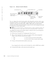
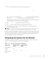
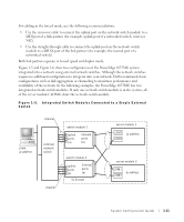
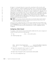
6 Type quit or exit to logout of the switch console. 7 Type ~. and press to return to the management console. Configuring a Dynamic Channel To configure a dynamic channel on all external ports from the serial connection on the network switch module, perform the following steps: 1 Type: #config (config)#interface ethernet 1/7 (config-if)#lacp (config-if)#exit 2 Repeat the commands in step 2 on ports 8, 9, and 10. A dynamic trunk of the four uplink ports is created by LACP. 3 Repeat steps 1 and 2 for the second network switch module. 4 To save the configuration, type #copy running-config startup-config. 5 Type quit or exit to logout of the switch console. 6 Type ~. and press to return to the management console. When both network switch modules are connected to the same subnet (see Figure 1-5), smart load balancing (SLB) can be used to "team" the LOMs to prevent spanning tree protocol from shutting down links and to provide load balancing and failover. SLB is configured through the Broadcom Advanced Server Program, which is on the Dell OpenManage Server Assistant CD. SLB is the only LOM teaming method supported on the PowerEdge 1655MC. NOTE: When you use the Broadcom drivers to configure an SLB team, the software only performs failover on the local link (the LOM on the server module). The SLB software cannot detect remote link failover at the uplink ports of the network switch module. To protect against link failure, configure channeling on multiple uplink ports on the network switch module. NOTE: When you use the Broadcom drivers to configure an SLB team on the server module, failure or removal of the network switch module does not cause disruption in network traffic. However, hot-adding of a network switch module causes temporary disruption of network traffic while the switch is booting since SLB software tries to balance the network traffic before the switch is ready. System Configuration Guide 1-13
-
 1
1 -
2
-
3
-
4
-
5
-
6
-
7
-
8
-
9
-
10
-
11
-
 12
12 -
 13
13 -
 14
14 -
 15
15 -
 16
16 -
 17
17 -
 18
18 -
 19
19 -
 20
20 -
 21
21 -
 22
22 -
23
-
24
-
25
-
26
-
27
-
28
-
29
-
30
-
31
-
32
-
33
-
34
-
35
-
36
-
37
-
38
-
39
-
40
-
41
-
42
-
43
-
44
-
45
-
46
-
47
-
48
-
49
-
50
-
51
-
52
-
53
-
54
-
55
-
56
-
57
-
58
-
59
-
60
-
61
-
62
-
63
-
64
-
65
-
66
-
67
-
68
-
69
-
70
-
71
-
72
-
73
-
74
-
75
-
76
-
77
-
78
-
79
-
80
-
81
-
82
-
83
-
84
-
85
-
86
-
87
-
88
-
89
-
90
-
91
-
92
-
93
-
94
-
95
-
96
-
97
-
98
-
99
-
100
-
101
-
102
-
103
-
104
-
105
-
106
-
107
-
108
-
109
-
110
-
111
-
112
-
113
-
114
-
115
-
116
-
117
-
118
-
119
-
120
-
121
-
122
-
123
-
124
-
125
-
126
-
127
-
128
-
129
-
130
-
131
-
132
-
133
-
134
-
135
-
136
-
137
-
138
-
139
-
140
-
141
-
142
-
143
-
144
-
145
-
146
-
147
-
148
-
149
-
150
-
151
-
152
-
153
-
154
-
155
-
156
-
157
-
158
-
159
-
160
-
161
-
162
-
163
-
164
-
165
-
166
-
167
-
168
-
169
-
170
-
171
-
172
-
173
-
174
-
175
-
176
-
177
-
178
-
179
-
180
-
181
-
182
-
183
-
184
-
185
-
186
-
187
-
188
-
189
-
190
-
191
-
192
-
193
-
194
-
195
-
196
-
197
-
198
-
199
-
200
-
201
-
202
-
203
-
204
-
205
-
206
-
207
-
208
-
209
-
210
-
211
-
212
-
213
-
214
-
215
-
216
-
217
-
218
-
219
-
220
-
221
-
222
-
223
 |
 |
