Dell PowerEdge VRTX Chassis Management Controller Version 1.0 for Dell PowerEd - Page 17
Indicator, Button, or Connector
 |
View all Dell PowerEdge VRTX manuals
Add to My Manuals
Save this manual to your list of manuals |
Page 17 highlights
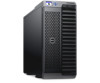
Item Indicator, Button, or Connector 10 PSU 1 11 PSU 2 A Front Panel view of the chassis is given here with a table that lists the parts and devices available in the CMC. Figure 1. Front-Panel Features And Indicators-3.5 Inch Hard Disk Drive Chassis Item Indicator, Button, or Connector 1 USB connectors (2) 2 LCD panel 3 LCD menu scroll buttons (4) 4 Selection ("check") button 5 Enclosure power-on indicator, power button 6 Hard disk drives (HDD) Description Allows a keyboard and mouse to be connected to the system. Provides system information and status, and error messages to indicate when the system is operating correctly or when the system needs attention. Moves the cursor in one-step increments. Selects and saves an item on the LCD screen and moves to the next screen. The power-on indicator glows when the enclosure power is on. The power button controls the PSU output to the system. 2.5 inch hard drive enclosure Up to twenty five 2.5 inch hot-swappable hard disk drives. 17
-
 1
1 -
2
-
3
-
4
-
5
-
6
-
7
-
8
-
9
-
10
-
11
-
 12
12 -
 13
13 -
 14
14 -
 15
15 -
 16
16 -
 17
17 -
 18
18 -
 19
19 -
 20
20 -
 21
21 -
 22
22 -
23
-
24
-
25
-
26
-
27
-
28
-
29
-
30
-
31
-
32
-
33
-
34
-
35
-
36
-
37
-
38
-
39
-
40
-
41
-
42
-
43
-
44
-
45
-
46
-
47
-
48
-
49
-
50
-
51
-
52
-
53
-
54
-
55
-
56
-
57
-
58
-
59
-
60
-
61
-
62
-
63
-
64
-
65
-
66
-
67
-
68
-
69
-
70
-
71
-
72
-
73
-
74
-
75
-
76
-
77
-
78
-
79
-
80
-
81
-
82
-
83
-
84
-
85
-
86
-
87
-
88
-
89
-
90
-
91
-
92
-
93
-
94
-
95
-
96
-
97
-
98
-
99
-
100
-
101
-
102
-
103
-
104
-
105
-
106
-
107
-
108
-
109
-
110
-
111
-
112
-
113
-
114
-
115
-
116
-
117
-
118
-
119
-
120
-
121
-
122
-
123
-
124
-
125
-
126
-
127
-
128
-
129
-
130
-
131
-
132
-
133
-
134
-
135
-
136
-
137
-
138
-
139
-
140
-
141
-
142
-
143
-
144
-
145
-
146
-
147
-
148
-
149
-
150
-
151
-
152
-
153
-
154
-
155
-
156
-
157
-
158
-
159
-
160
-
161
-
162
-
163
-
164
-
165
-
166
-
167
-
168
-
169
-
170
-
171
-
172
-
173
-
174
-
175
-
176
-
177
-
178
-
179
-
180
-
181
-
182
-
183
-
184
-
185
-
186
-
187
-
188
-
189
-
190
-
191
-
192
-
193
 |
 |
