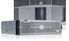
Dell PowerVault DL4000 Dell PowerVault DL4000 Systems Owner's Manual - Page 33
Mode-Specific Guidelines, Memory Configuration, Removing Memory Modules
 |
View all Dell PowerVault DL4000 manuals
Add to My Manuals
Save this manual to your list of manuals |
Page 33 highlights
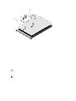
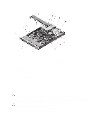
channel 2: slots B3, B7, and B11 channel 3: slots B4, B8, and B12 Mode-Specific Guidelines Four memory channels are allocated to each processor. The allowable configurations depend on the memory mode selected. NOTE: x4 and x8 DRAM based DIMMs can be mixed providing support for RAS features. However, all guidelines for specific RAS features must be followed. x4 DRAM based DIMMs retain Single Device Data Correction (SDDC) in memory optimized (independent channel) mode. x8 DRAM based DIMMs require Advanced ECC mode to gain SDDC. The following sections provide additional slot population guidelines for each mode. Memory Optimized (Independent Channel) Mode This mode supports SDDC only for memory modules that use x4 device width and does not impose any specific slot population requirements. Memory Configuration The following table shows the memory configuration for a two processor configuration. NOTE: 2R in the following table indicates single DIMMs. Table 1. Memory Configuration System DIMM Size (in Number of Capacity (in GB) GB) DIMMs 32 4 8 DIMM Rank, Organization, and Frequency 2R, x8, 1333 MT/s, DIMM Slot Population A1, A2, A3, A4 B1, B2, B3, B4 Removing Memory Modules WARNING: The memory modules are hot to the touch for some time after the system has been powered down. Allow time for the memory modules to cool before handling them. Handle the memory modules by the card edges and avoid touching the components on the memory module. CAUTION: Many repairs may only be done by a certified service technician. You should only perform troubleshooting and simple repairs as authorized in your product documentation, or as directed by the online or telephone service and support team. Damage due to servicing that is not authorized by Dell is not covered by your warranty. Read and follow the safety instructions that came with the product. CAUTION: To ensure proper system cooling, memory-module blanks must be installed in any memory socket that is not occupied. Remove memory-module blanks only if you intend to install memory in those sockets. 1. Turn off the system, including any attached peripherals, and disconnect the system from the electrical outlet and peripherals. 2. Open the system. 3. Remove the cooling shroud. 4. Locate the appropriate memory module socket(s). 33
-
 1
1 -
2
-
3
-
4
-
5
-
6
-
7
-
8
-
9
-
10
-
11
-
12
-
13
-
14
-
15
-
16
-
17
-
18
-
19
-
20
-
21
-
22
-
23
-
24
-
25
-
26
-
27
-
 28
28 -
 29
29 -
 30
30 -
 31
31 -
 32
32 -
 33
33 -
 34
34 -
 35
35 -
 36
36 -
 37
37 -
 38
38 -
39
-
40
-
41
-
42
-
43
-
44
-
45
-
46
-
47
-
48
-
49
-
50
-
51
-
52
-
53
-
54
-
55
-
56
-
57
-
58
-
59
-
60
-
61
-
62
-
63
-
64
-
65
-
66
-
67
-
68
-
69
-
70
-
71
-
72
-
73
-
74
-
75
-
76
-
77
-
78
-
79
-
80
-
81
-
82
-
83
-
84
-
85
-
86
-
87
-
88
-
89
-
90
-
91
-
92
-
93
-
94
-
95
-
96
-
97
-
98
-
99
-
100
-
101
 |
 |
