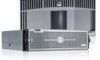
Dell PowerVault DL4000 Dell PowerVault DL4000 Systems Owner's Manual - Page 63
System Board, Removing The System Board
 |
View all Dell PowerVault DL4000 manuals
Add to My Manuals
Save this manual to your list of manuals |
Page 63 highlights
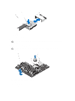
NOTE: To locate the connectors on the system board, see System Board Connectors. 5. Connect the control panel cable to the connectors on the system board (J_CP and J_FP_USB) and the hard-drive expander card. NOTE: Ensure that the control panel cable inside the system is routed along the chassis wall and secured using the cable securing bracket. 6. Close the system. 7. Reconnect the system to its electrical outlet and turn the system on, including any attached peripherals. 8. If applicable, install the front bezel. System Board Removing The System Board CAUTION: Many repairs may only be done by a certified service technician. You should only perform troubleshooting and simple repairs as authorized in your product documentation, or as directed by the online or telephone service and support team. Damage due to servicing that is not authorized by Dell is not covered by your warranty. Read and follow the safety instructions that came with the product. CAUTION: If you are using the Trusted Program Module (TPM) with an encryption key, you may be prompted to create a recovery key during program or System Setup. Be sure to create and safely store this recovery key. If you replace this system board, you must supply the recovery key when you restart your system or program before you can access the encrypted data on your hard drives. 1. Turn off the system, including any attached peripherals, and disconnect the system from the electrical outlet. 2. If installed, remove the front bezel. 3. Open the system. 4. Remove the following: a) cooling shroud b) memory modules c) cooling fans d) power supply(s) e) all expansion-card risers WARNING: The heat sink is hot to touch for some time after the system has been powered down. Ensure that you do not touch the heat sink(s) while removing the system board. f) heat sink(s) and processors(s) g) all expansion cards and the integrated storage controller card h) network daughter card i) internal dual SD module j) internal USB key (if installed) k) hot-swap hard drives l) hard-drive backplane CAUTION: To avoid damaging the mini SAS cable and connector, follow the correct procedure in step 5 when removing the mini SAS cable from the system board. 5. Disconnect the mini SAS cable from the system board: a) Push the mini SAS cable connector to slide it further into the connector (J_SASX8) on the system board. b) Press down and hold the metal tab on the mini SAS cable connector. 63
-
 1
1 -
2
-
3
-
4
-
5
-
6
-
7
-
8
-
9
-
10
-
11
-
12
-
13
-
14
-
15
-
16
-
17
-
18
-
19
-
20
-
21
-
22
-
23
-
24
-
25
-
26
-
27
-
28
-
29
-
30
-
31
-
32
-
33
-
34
-
35
-
36
-
37
-
38
-
39
-
40
-
41
-
42
-
43
-
44
-
45
-
46
-
47
-
48
-
49
-
50
-
51
-
52
-
53
-
54
-
55
-
56
-
57
-
 58
58 -
 59
59 -
 60
60 -
 61
61 -
 62
62 -
 63
63 -
 64
64 -
 65
65 -
 66
66 -
 67
67 -
 68
68 -
69
-
70
-
71
-
72
-
73
-
74
-
75
-
76
-
77
-
78
-
79
-
80
-
81
-
82
-
83
-
84
-
85
-
86
-
87
-
88
-
89
-
90
-
91
-
92
-
93
-
94
-
95
-
96
-
97
-
98
-
99
-
100
-
101
 |
 |
