Dell PowerVault DL4000 Dell PowerVault DL4000 Systems Owner's Manual - Page 8
Diagnostic Indicators, Mini USB connector
 |
View all Dell PowerVault DL4000 manuals
Add to My Manuals
Save this manual to your list of manuals |
Page 8 highlights
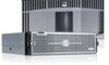
Item Indicator, Button, or Icon Connector 6 Mini USB connector 7 Hard drives (10) 8 Information tag Description If the system stops responding during POST, press and hold the system ID button for more than five seconds to enter BIOS progress mode. To reset the iDRAC (if not disabled in F2 iDRAC setup) press and hold the button for more than 15 seconds. Allows you to connect USB devices to the system. The port is USB 2.0-compliant. Up to ten 2.5 inch hot-swappable hard drives. A slide-out label panel, which allows you to record system information, such as Service Tag, NIC, MAC address, and so on as per your need. Diagnostic Indicators The diagnostic indicators on the system front panel display error status during system startup. The following section describes system conditions and possible corrective actions associated with these indicators: Electrical indicator Condition Corrective Action The indicator blinks amber if the system experiences an electrical error (for example, voltage out of range, or a failed power supply or voltage regulator). See the System Event Log or system messages for the specific issue. If it is due to a problem with the power supply, check the LED on the power supply. Re-seat the power supply by removing and reinstalling it. If the problem persists, see Getting Help. Temperature indicator Condition The indicator blinks amber if the system experiences a thermal error (for example, a temperature out of range or fan failure). Corrective Action Ensure that none of the following conditions exist: • A cooling fan is removed or has failed. • System cover, cooling shroud, EMI filler panel, memory- module blank, or back-filler bracket is removed. • Ambient temperature is too high. • External airflow is obstructed. See Getting Help. 8
-
 1
1 -
2
-
 3
3 -
 4
4 -
 5
5 -
 6
6 -
 7
7 -
 8
8 -
 9
9 -
 10
10 -
 11
11 -
 12
12 -
 13
13 -
14
-
15
-
16
-
17
-
18
-
19
-
20
-
21
-
22
-
23
-
24
-
25
-
26
-
27
-
28
-
29
-
30
-
31
-
32
-
33
-
34
-
35
-
36
-
37
-
38
-
39
-
40
-
41
-
42
-
43
-
44
-
45
-
46
-
47
-
48
-
49
-
50
-
51
-
52
-
53
-
54
-
55
-
56
-
57
-
58
-
59
-
60
-
61
-
62
-
63
-
64
-
65
-
66
-
67
-
68
-
69
-
70
-
71
-
72
-
73
-
74
-
75
-
76
-
77
-
78
-
79
-
80
-
81
-
82
-
83
-
84
-
85
-
86
-
87
-
88
-
89
-
90
-
91
-
92
-
93
-
94
-
95
-
96
-
97
-
98
-
99
-
100
-
101
 |
 |
