Dell PowerVault DL4000 Dell PowerVault DL4000 Systems Owner's Manual - Page 64
Removing and Installing the System Board
 |
View all Dell PowerVault DL4000 manuals
Add to My Manuals
Save this manual to your list of manuals |
Page 64 highlights
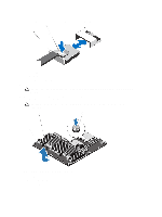
c) Pull the mini SAS cable out of the connector on the system board. a. mini SAS cable connector b. metal tab c. connector on the system board 6. Disconnect all other cables from the system board. CAUTION: Take care not to damage the system identification button while removing the system board from the chassis. 7. Grasp the system-board holder, lift the blue release pin, slide the system board toward the front of the system, and lift the system board out of the chassis. CAUTION: Do not lift the system board assembly by grasping a memory module, processor, or other components. Figure 30. Removing and Installing the System Board 1. system board 2. system-board holder 3. release pin 64
-
 1
1 -
2
-
3
-
4
-
5
-
6
-
7
-
8
-
9
-
10
-
11
-
12
-
13
-
14
-
15
-
16
-
17
-
18
-
19
-
20
-
21
-
22
-
23
-
24
-
25
-
26
-
27
-
28
-
29
-
30
-
31
-
32
-
33
-
34
-
35
-
36
-
37
-
38
-
39
-
40
-
41
-
42
-
43
-
44
-
45
-
46
-
47
-
48
-
49
-
50
-
51
-
52
-
53
-
54
-
55
-
56
-
57
-
58
-
 59
59 -
 60
60 -
 61
61 -
 62
62 -
 63
63 -
 64
64 -
 65
65 -
 66
66 -
 67
67 -
 68
68 -
 69
69 -
70
-
71
-
72
-
73
-
74
-
75
-
76
-
77
-
78
-
79
-
80
-
81
-
82
-
83
-
84
-
85
-
86
-
87
-
88
-
89
-
90
-
91
-
92
-
93
-
94
-
95
-
96
-
97
-
98
-
99
-
100
-
101
 |
 |

c)
Pull the mini SAS cable out of the connector on the system board.
a. mini SAS cable connector
b. metal tab
c. connector on the system board
6.
Disconnect all other cables from the system board.
CAUTION: Take care not to damage the system identification button while removing the system board from
the chassis.
7.
Grasp the system-board holder, lift the blue release pin, slide the system board toward the front of the system, and
lift the system board out of the chassis.
CAUTION: Do not lift the system board assembly by grasping a memory module, processor, or other
components.
Figure 30. Removing and Installing the System Board
1. system board
2. system-board holder
3. release pin
64