Dell Precision Tower 7810 Dell Precision Tower 7810 Owners Manual - Page 57
Troubleshooting Your Computer, Diagnostic LEDs - motherboard
 |
View all Dell Precision Tower 7810 manuals
Add to My Manuals
Save this manual to your list of manuals |
Page 57 highlights
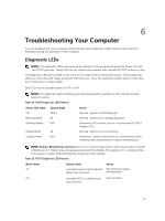
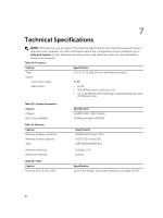
6 Troubleshooting Your Computer You can troubleshoot your computer using indicators like Diagnostic Lights, Beep Codes, and Error Messages during the operation of the computer. Diagnostic LEDs NOTE: The diagnostic LEDs only serve as an indicator of the progress through the Power-On Self Test (POST) process. These LEDs do not indicate the problem that caused the POST routine to stop. The diagnostic LEDs are located on the front of the chassis next to the power button. These diagnostic LEDs are only active and visible during the POST process. Once the operating system starts to load, they turn off and are no longer visible. Each LED has two possible states of OFF or ON. NOTE: The diagnostic lights will blink when the power button is amber or off, and will not blink when it is white. Table 14. POST Diagnostic LED Patterns Power LED State Off Blinking White Blinking Amber System State S5/S4 S3 N/A Steady White S0 Steady Amber N/A Notes Normal- System is Off/Hibernate Normal- System is in Standby/Suspend Abnormal- PSU cannot turn on, recommend PSU BIST. Replace PSU. Normal- System is on functioning Abnormal- System cannot turn on, recommend check motherboard components or replace motherboard. NOTE: Amber LED blinking schemepattern is 2 or 3 blinks followed by a short pause then X number of blinks up to 7. Pattern has a long pause inserted in the middle. For example 2,3 = 2 amber blinks, short pause, 3 amber blinks followed by long pause then repeats. Table 15. POST Diagnostic LED Patterns Blink Patter 2,1 System State A possible system motherboard failure has occurred. Notes Recommend replace motherboard. 2,2 A possible PSU or cabling issue Run PSU BIST. has occurred. 57
-
 1
1 -
2
-
3
-
4
-
5
-
6
-
7
-
8
-
9
-
10
-
11
-
12
-
13
-
14
-
15
-
16
-
17
-
18
-
19
-
20
-
21
-
22
-
23
-
24
-
25
-
26
-
27
-
28
-
29
-
30
-
31
-
32
-
33
-
34
-
35
-
36
-
37
-
38
-
39
-
40
-
41
-
42
-
43
-
44
-
45
-
46
-
47
-
48
-
49
-
50
-
51
-
 52
52 -
 53
53 -
 54
54 -
 55
55 -
 56
56 -
 57
57 -
 58
58 -
 59
59 -
 60
60 -
 61
61 -
 62
62 -
63
-
64
-
65
-
66
-
67
-
68
 |
 |