Dell XPS 13 9315 XPS 13 9315 / XPS 9315 Service Manual
Dell XPS 13 9315 Manual
 |
View all Dell XPS 13 9315 manuals
Add to My Manuals
Save this manual to your list of manuals |
Dell XPS 13 9315 manual content summary:
- Dell XPS 13 9315 | XPS 13 9315 / XPS 9315 Service Manual - Page 1
XPS 13 9315 / XPS 9315 Service Manual Regulatory Model: P153G Regulatory Type: P153G001 May 2022 Rev. A01 - Dell XPS 13 9315 | XPS 13 9315 / XPS 9315 Service Manual - Page 2
and tells you how to avoid the problem. WARNING: A WARNING indicates a potential for property damage, personal injury, or death. © 2022 Dell Inc. or its subsidiaries. All rights reserved. Dell Technologies, Dell, and other trademarks are trademarks of Dell Inc. or its subsidiaries. Other trademarks - Dell XPS 13 9315 | XPS 13 9315 / XPS 9315 Service Manual - Page 3
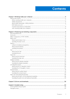
service kit ...7 Transporting sensitive components...8 After working inside your computer...8 Chapter 2: Removing and installing components 9 Recommended tools...9 Screw list...9 Major components of XPS 13 9315...10 Base cover...12 Removing the base cover...12 Installing the base cover...14 Battery - Dell XPS 13 9315 | XPS 13 9315 / XPS 9315 Service Manual - Page 4
Ubuntu...58 Updating the BIOS from the F12 One-Time boot menu 58 Chapter 5: Troubleshooting...60 Handling swollen Lithium-ion batteries...60 Locate the Service Tag or Express Service Code of your Dell computer 60 System diagnostic lights...61 SupportAssist diagnostics...61 Built-in self-test (BIST - Dell XPS 13 9315 | XPS 13 9315 / XPS 9315 Service Manual - Page 5
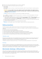
troubleshooting and repairs as authorized or directed by the Dell technical assistance team. Damage due to servicing that is not authorized by Dell is not covered by your warranty. See the safety instructions when handling Lithium-ion batteries in laptops. Swollen batteries should not be used - Dell XPS 13 9315 | XPS 13 9315 / XPS 9315 Service Manual - Page 6
Service Mode or the computer does not support Service Mode then proceed to disconnect the battery cable. To disconnect the battery cable, follow the steps in Removing the battery electrocuted. Standby power Dell products with standby power as intermittent problems or a shortened product life span. As - Dell XPS 13 9315 | XPS 13 9315 / XPS 9315 Service Manual - Page 7
higher than in previous Dell products. For this The more difficult type of damage to recognize and troubleshoot is the intermittent (also called latent or "walking wounded mat, and the hardware is known as bonding. Use only Field Service kits with a wrist strap, mat, and bonding wire. Never use - Dell XPS 13 9315 | XPS 13 9315 / XPS 9315 Service Manual - Page 8
for safe transport. ESD protection summary It is recommended that all field service technicians use the traditional wired ESD grounding wrist strap and protective anti-static mat at all times when servicing Dell products. In addition, it is critical that technicians keep sensitive parts separate - Dell XPS 13 9315 | XPS 13 9315 / XPS 9315 Service Manual - Page 9
ordered. Table 1. Screw list Component Secured to Screw type Base cover Palm-rest and keyboard M2x3, Torx 5 assembly Quantity 8 Screw image Battery Palm-rest and keyboard M2x3 8 assembly Fan System board M1.6x2.5 2 Heat sink System board M2x3 4 Display-assembly System board M1 - Dell XPS 13 9315 | XPS 13 9315 / XPS 9315 Service Manual - Page 10
keyboard M1.6x2.8 1 assembly System board Palm-rest and keyboard M1.6x1.5 5 assembly System board Palm-rest and keyboard M1.6x2.3 1 assembly Major components of XPS 13 9315 The following image shows the major components of XPS 13 9315. Screw image 10 Removing and installing components - Dell XPS 13 9315 | XPS 13 9315 / XPS 9315 Service Manual - Page 11
2. I/O daughter-board 3. Battery 4. I/O daughter-board power cable 5. Heat sink 6. Palm-rest and keyboard assembly 7. Display assembly 8. Fan 9. I/O daughter-board interposer board 10. System-board interposer board 11. System board 12. Display-assembly interposer board 13. I/O daughter-board cable - Dell XPS 13 9315 | XPS 13 9315 / XPS 9315 Service Manual - Page 12
to warranty coverages purchased by the customer. Contact your Dell sales representative for purchase options. Base cover Removing the base in Before working inside your computer. NOTE: Ensure that your computer is in Service Mode. For more information, see Step 6 in Before working inside your - Dell XPS 13 9315 | XPS 13 9315 / XPS 9315 Service Manual - Page 13
of the base cover and push the base cover slightly to the rear of the computer. NOTE: This action releases the base cover from the hooks that are on the palm-rest and keyboard assembly. NOTE: Do not pull on , replace the thermal pad to its original position. Removing and installing components 13 - Dell XPS 13 9315 | XPS 13 9315 / XPS 9315 Service Manual - Page 14
Installing the base cover Prerequisites If you are replacing a component, remove the existing component before performing the installation process. About this task The following image(s) indicate the location of the base cover and provides a visual representation of the installation procedure. 14 - Dell XPS 13 9315 | XPS 13 9315 / XPS 9315 Service Manual - Page 15
Removing and installing components 15 - Dell XPS 13 9315 | XPS 13 9315 / XPS 9315 Service Manual - Page 16
, do not try to release it as puncturing, bending, or crushing a lithium-ion battery can be dangerous. In such an instance, contact Dell technical support for assistance. See www.dell.com/contactdell. ● Always purchase genuine batteries from www.dell.com or authorized Dell partners and resellers - Dell XPS 13 9315 | XPS 13 9315 / XPS 9315 Service Manual - Page 17
connector. 2. Remove the eight screws (M1.6x2.5) that secure the battery to the palm-rest and keyboard assembly. 3. Lift the battery off the palm-rest and keyboard assembly. Installing the battery Prerequisites If you are replacing a component, remove the existing component before performing the - Dell XPS 13 9315 | XPS 13 9315 / XPS 9315 Service Manual - Page 18
on the palm-rest and keyboard assembly. 3. Replace the eight screws (M1.6x2.5) that secure the battery to the palm-rest and keyboard assembly. 4. Connect the battery cable to the system board. Next steps 1. Install the base cover. 2. Follow the procedure in After working inside your computer. Fan - Dell XPS 13 9315 | XPS 13 9315 / XPS 9315 Service Manual - Page 19
power cable connector out to disconnect the I/O daughter-board power cable from the I/O daughter board. 3. Remove the I/O daughter-board power cable from the two routing guide below the fan, and peel off the tape from the fan. 4. Lift the latch of fan cable connector, use the pull tab of the fan - Dell XPS 13 9315 | XPS 13 9315 / XPS 9315 Service Manual - Page 20
the tape that secures the I/O daughter-board power cable to the fan. 6. Place the I/O daughter-board power cable back to the two routing guides below the fan. 7. Connect the I/O daughter-board power cable to the I/O daughter-board. Next steps 1. Install the base cover. 2. Follow the procedure in - Dell XPS 13 9315 | XPS 13 9315 / XPS 9315 Service Manual - Page 21
Heat sink Removing the heat sink Prerequisites 1. Follow the procedure in Before working inside your computer. 2. Remove the base cover. About this task CAUTION: The heat sink may become hot during normal operation. Allow sufficient time for the heat sink to cool before you touch it. NOTE: For - Dell XPS 13 9315 | XPS 13 9315 / XPS 9315 Service Manual - Page 22
NOTE: If either the system board or the heat sink is replaced, use the thermal grease that is provided in the kit to ensure that thermal conductivity is achieved. The following image(s) indicate the location of the heat sink and provides a visual representation of the installation procedure. Steps - Dell XPS 13 9315 | XPS 13 9315 / XPS 9315 Service Manual - Page 23
Removing and installing components 23 - Dell XPS 13 9315 | XPS 13 9315 / XPS 9315 Service Manual - Page 24
Steps 1. Open the display assembly to a 90-degree angle and place the computer on the edge of a flat surface. 2. Remove the two screws (M1.6x3.5) that secure the camera and display-assembly cable to the display-assembly interposer board on the system board. 3. Lift the camera and display-assembly - Dell XPS 13 9315 | XPS 13 9315 / XPS 9315 Service Manual - Page 25
4. Remove the four screws (M1.6x2.3) that secure the two display-assembly cable brackets to the palm-rest and keyboard assembly. 5. Lift the display-assembly cable brackets off the system board. 6. Remove the six screws (M2.5x4.3) that secure the hinges of the display assembly to the palm-rest and - Dell XPS 13 9315 | XPS 13 9315 / XPS 9315 Service Manual - Page 26
About this task The following image(s) indicate the location of the display assembly and provides a visual representation of the installation procedure. 26 Removing and installing components - Dell XPS 13 9315 | XPS 13 9315 / XPS 9315 Service Manual - Page 27
Steps 1. Place the palm-rest and keyboard assembly at the edge of a flat table. 2. Open the hinges of the display assembly to a 90-degree angle. 3. Align the screw holes of the palm-rest and keyboard assembly to the screws holes on the hinges of the display assembly. 4. Replace the six screws (M2. - Dell XPS 13 9315 | XPS 13 9315 / XPS 9315 Service Manual - Page 28
9. Replace the two screws (M1.6x3.5) that secure the camera and display-assembly cable to the display-assembly interposer board on the system board. Next steps 1. Install the base cover. 2. Follow the procedure in After working inside your computer. I/O daughter-board Removing the I/O daughter-board - Dell XPS 13 9315 | XPS 13 9315 / XPS 9315 Service Manual - Page 29
Steps 1. Remove the screw (M1.6x2.8) that secures the I/O daughter-board cable to the I/O daughter-board interposer board. 2. Remove the I/O daughter-board cable from the I/O daughter-board interposer board. 3. Use the pull tab on the right speaker cable to disconnect the right speaker cable from - Dell XPS 13 9315 | XPS 13 9315 / XPS 9315 Service Manual - Page 30
Installing the I/O daughter-board Prerequisites If you are replacing a component, remove the existing component before performing the installation process. About this task The following image(s) indicate the location of the I/O daughter-board and provides a visual representation of the installation - Dell XPS 13 9315 | XPS 13 9315 / XPS 9315 Service Manual - Page 31
board Removing the system board Prerequisites 1. Follow the procedure in Before working inside your computer. 2. Remove the base cover. 3. Remove the battery. 4. Remove the display assembly. 5. Remove the heat sink. About this task The following image indicates the connectors and component(s) on - Dell XPS 13 9315 | XPS 13 9315 / XPS 9315 Service Manual - Page 32
Figure 1. System-board connectors 1. Fan cable connector 3. Battery cable connector 5. Touch-panel cable connector 2. Wireless card 4. I/O daughter-board power cable connector 6. Camera-assembly cable connector The following image(s) indicate the location of the - Dell XPS 13 9315 | XPS 13 9315 / XPS 9315 Service Manual - Page 33
Steps 1. Remove the screw (M1.6x2.3) that secures the wireless-module bracket to the system board. 2. Lift the wireless-module bracket off the system board. 3. Remove the screw (M1.6x2.8) that secures the I/O daughter-board cable to the system board. 4. Remove the system-board interposer board off - Dell XPS 13 9315 | XPS 13 9315 / XPS 9315 Service Manual - Page 34
Figure 2. System-board connectors 1. Fan cable connector 3. Battery cable connector 5. Touch-panel cable connector 2. Wireless card 4. I/O daughter-board power cable connector 6. I/O daughter-board cable connector The following image(s) indicate the location of the - Dell XPS 13 9315 | XPS 13 9315 / XPS 9315 Service Manual - Page 35
(M1.6x2.3) that secures the wireless-module bracket to the system board. Next steps 1. Install the heat sink. 2. Install the display assembly. 3. Install the battery. 4. Install the base cover. 5. Follow the procedure in After working inside your computer. Removing and installing components 35 - Dell XPS 13 9315 | XPS 13 9315 / XPS 9315 Service Manual - Page 36
palm-rest and keyboard assembly Prerequisites 1. Follow the procedure in Before working inside your computer. 2. Remove the base cover. 3. Remove the battery. 4. Remove the fan. 5. Remove the display assembly. 6. Remove the I/O daughter-board. 7. Remove the system board. NOTE: The system board can - Dell XPS 13 9315 | XPS 13 9315 / XPS 9315 Service Manual - Page 37
system board can be installed with the attached heat sink. 2. Install the I/O daughter-board. 3. Install the display assembly. 4. Install the fan. 5. Install the battery. 6. Install the base cover. 7. Follow the procedure in After working inside your computer. Removing and installing components 37 - Dell XPS 13 9315 | XPS 13 9315 / XPS 9315 Service Manual - Page 38
3 Drivers and downloads When troubleshooting, downloading or installing drivers it is recommended that you read the Dell Knowledge Based article, Drivers and Downloads FAQ 000123347. 38 Drivers and downloads - Dell XPS 13 9315 | XPS 13 9315 / XPS 9315 Service Manual - Page 39
directly to a specific device (for example: USB flash drive, external optical drive, or external storage device). During the Power-on Self Test (POST), when the Dell logo appears, you can: System setup 39 - Dell XPS 13 9315 | XPS 13 9315 / XPS 9315 Service Manual - Page 40
System setup options-Overview menu Overview XPS 13 9315/XPS 9315 BIOS Version Displays the BIOS version number. Service Tag Displays the Service Tag of the computer. Asset Tag Displays the Asset Tag of the computer. Manufacture Date Displays the manufacture date of the computer. Ownership - Dell XPS 13 9315 | XPS 13 9315 / XPS 9315 Service Manual - Page 41
Table 3. System setup options-Overview menu (continued) Overview AC Adapter Displays whether an AC adapter is connected. If connected, displays the type of AC adapter that is connected. Processor Information Processor Type Displays the processor type. Maximum Clock Speed Displays the maximum - Dell XPS 13 9315 | XPS 13 9315 / XPS 9315 Service Manual - Page 42
Enable Secure Boot option is enabled. For additional security, Dell Technologies recommends keeping the Secure Boot option enabled to -Integrated Devices menu Integrated Devices Date/Time Date Sets the computer date in MM/DD/YYYY format. Changes to the date format take effect immediately. Time - Dell XPS 13 9315 | XPS 13 9315 / XPS 9315 Service Manual - Page 43
used during BIOS Pre-boot. By default, the Enable Thunderbolt Boot Support option is disabled. Enable Thunderbolt (and PCIe behind TBT) pre Type-C Dock Type-C Dock Override Enables or disables to use connected Type-C Dell Dock to provide data stream with external USB ports disabled. When Type-C - Dell XPS 13 9315 | XPS 13 9315 / XPS 9315 Service Manual - Page 44
-Only Mode option is disabled. Table 7. System setup options-Display menu Display Display Brightness Brightness on battery power Enables to set the screen brightness when the computer is running on battery power. By default, the screen brightness is set to 50 when the computer is running on - Dell XPS 13 9315 | XPS 13 9315 / XPS 9315 Service Manual - Page 45
Battery Charged maximizes battery health while still supporting heavy use during the work day. By default, the Enable Advanced Battery Charge performance, noise, and temperature. USB Wake Support Wake on Dell USB-C Dock When enabled, connecting a Dell USB-C Dock wakes the computer from Standby - Dell XPS 13 9315 | XPS 13 9315 / XPS 9315 Service Manual - Page 46
Shift Technology Enables or disables the Intel Speed Shift Technology support. When enabled, the operating system selects the appropriate processor , the TPM On option is enabled. For additional security, Dell Technologies recommends keeping TPM enabled to allow these security technologies to - Dell XPS 13 9315 | XPS 13 9315 / XPS 9315 Service Manual - Page 47
hash algorithm to extend measurements into the TPM PCRs during BIOS boot. By default, the SHA-256 option is enabled. For additional security, Dell Technologies recommends keeping the SHA-256 option enabled. Clear When enabled, the Clear option clears information stored in the TPM after exiting the - Dell XPS 13 9315 | XPS 13 9315 / XPS 9315 Service Manual - Page 48
Detection option is enabled. For additional security, Dell Technologies recommends keeping the Chassis Intrusion Detection option supports the Authenticated BIOS Manageability Interface (ABI) for managing the BIOS configuration changes. To support service from Absolute software. 48 System setup - Dell XPS 13 9315 | XPS 13 9315 / XPS 9315 Service Manual - Page 49
Table 10. System setup options-Security menu (continued) Security By default, the Absolute option is enabled. For additional security, Dell Technologies recommends keeping the Absolute option enabled. WARNING: The 'Permanently Disabled' option can only be selected once. When 'Permanently Disabled' - Dell XPS 13 9315 | XPS 13 9315 / XPS 9315 Service Manual - Page 50
If the system and hard drive passwords are set to the same value, the hard drive unlocks after the correct system password is entered. Dell Technologies recommends using a hard drive password to protect unauthorized data access. Owner Password The Owner Password is typically used when a system is - Dell XPS 13 9315 | XPS 13 9315 / XPS 9315 Service Manual - Page 51
an end user to provide their own password. By default, the Allow Non-Admin Password Changes option is disabled. For additional security, Dell Technologies recommends keeping the Allow NonAdmin Password Changes option disabled. Non-Admin Setup Changes The Non-Admin Setup Changes option allows an - Dell XPS 13 9315 | XPS 13 9315 / XPS 9315 Service Manual - Page 52
Dell operating system Recovery Tool. By default, the Dell Auto OS Recovery Threshold value is set to 2. Table 13. System setup options-System Management menu System Management Service Tag Displays the Service every day or on a preselected date and time. This option can be configured only - Dell XPS 13 9315 | XPS 13 9315 / XPS 9315 Service Manual - Page 53
Table 13. System Backlight Timeout on Battery Sets the timeout value for the keyboard backlight when the computer is running only on the battery power. The LSI RAID (CTRL+C) Option ROMs. Other pre-boot Option ROMs, which support entry using a key sequence, are not affected by this setting. Table 15 - Dell XPS 13 9315 | XPS 13 9315 / XPS 9315 Service Manual - Page 54
an external PS/2 mouse is present. Sign of Life Early Logo Display Display Logo Sign of Life. By default, the Early Logo Display option Enable Pre-Boot DMA Support option is enabled. For additional security, Dell Technologies recommends keeping the Enable PreBoot DMA Support option enabled. NOTE: - Dell XPS 13 9315 | XPS 13 9315 / XPS 9315 Service Manual - Page 55
. NOTE: This option is not available when the virtualization setting for IOMMU is disabled (VT-d/AMD Vi). By default, the Enable OS Kernel DMA Support option is enabled. NOTE: This option is provided only for compatibility purposes, since some older hardware is not DMA capable. Table 17. System - Dell XPS 13 9315 | XPS 13 9315 / XPS 9315 Service Manual - Page 56
Table 18. System setup options-System Logs menu (continued) System Logs Clear BIOS Event Log Allows you to select option to keep or clear BIOS events logs. By default, the Keep Log option is selected. Thermal Event Log Clear Thermal Event Log Allows you to select option to keep or clear - Dell XPS 13 9315 | XPS 13 9315 / XPS 9315 Service Manual - Page 57
BIOS in Windows Steps 1. Go to www.dell.com/support. 2. Click Product support. In the Search support box, enter the Service Tag of your computer, and then click Search the on-screen instructions. For more information, see knowledge base article 000124211 at www.dell.com/support. System setup 57 - Dell XPS 13 9315 | XPS 13 9315 / XPS 9315 Service Manual - Page 58
press Enter. The BIOS Update Utility appears. 8. Follow the on-screen instructions to complete the BIOS update. Updating the BIOS in Linux and Ubuntu To Dell Support website and copied to the root of the USB drive ● AC power adapter that is connected to the computer ● Functional computer battery to - Dell XPS 13 9315 | XPS 13 9315 / XPS 9315 Service Manual - Page 59
7. The computer will restart after the BIOS update is completed. System setup 59 - Dell XPS 13 9315 | XPS 13 9315 / XPS 9315 Service Manual - Page 60
Service Code. To view relevant support resources for your Dell computer, we recommend entering the Service Tag or Express Service Code at www.dell.com/support. For more information on how to find the Service Tag for your computer, see Locate the Service Tag for your Dell Laptop. 60 Troubleshooting - Dell XPS 13 9315 | XPS 13 9315 / XPS 9315 Service Manual - Page 61
power and battery-charge status light The following table lists the status of your computer based on the Service LED. Table 20. Service LED Power and battery-charge status completed successfully ● View error messages that indicate if problems were encountered during the test Troubleshooting 61 - Dell XPS 13 9315 | XPS 13 9315 / XPS 9315 Service Manual - Page 62
board. 3. Replace the system board to fix the issue. NOTE: The battery status LED will not illuminate if there is no failure present with the system board. If further troubleshooting is required, proceed with the applicable Guided Resolution for No Power/No POST, etc. Display panel power rail built - Dell XPS 13 9315 | XPS 13 9315 / XPS 9315 Service Manual - Page 63
1. Press and hold the D key and then press the power button. 2. Release both the D key and the power button when the computer begins POST. 3. detected with system board. Solid amber Table 22. BIST outcome Indicates a problem with the system board. L-BIST Off No fault detected with system board - Dell XPS 13 9315 | XPS 13 9315 / XPS 9315 Service Manual - Page 64
Support website to troubleshoot and fix your computer when it fails to boot into their primary operating system due to software or hardware failures. For more information about the Dell SupportAssist OS Recovery, see Dell SupportAssist OS Recovery User's Guide at www.dell.com/serviceabilitytools - Dell XPS 13 9315 | XPS 13 9315 / XPS 9315 Service Manual - Page 65
2 in Removing the battery). 4. Press and dell.com/support. Backup media and recovery options It is recommended to create a recovery drive to troubleshoot and fix problems that may occur with Windows. Dell the system date and time. The following items are unaffected by the RTC reset: ● Service Tag ● - Dell XPS 13 9315 | XPS 13 9315 / XPS 9315 Service Manual - Page 66
about your computer through videos, manuals and documents. Your Dell computer is uniquely identified by a Service Tag or Express Service Code. To view relevant support resources for your Dell computer, enter the Service Tag or Express Service Code at www.dell.com/support. For more information on
-
 1
1 -
 2
2 -
 3
3 -
 4
4 -
 5
5 -
 6
6 -
 7
7 -
8
-
9
-
10
-
11
-
12
-
13
-
14
-
15
-
16
-
17
-
18
-
19
-
20
-
21
-
22
-
23
-
24
-
25
-
26
-
27
-
28
-
29
-
30
-
31
-
32
-
33
-
34
-
35
-
36
-
37
-
38
-
39
-
40
-
41
-
42
-
43
-
44
-
45
-
46
-
47
-
48
-
49
-
50
-
51
-
52
-
53
-
54
-
55
-
56
-
57
-
58
-
59
-
60
-
61
-
62
-
63
-
64
-
65
-
66
 |
 |

XPS 13 9315 / XPS 9315
Service Manual
Regulatory Model: P153G
Regulatory Type: P153G001
May 2022
Rev. A01