Dell XPS 13 9315 XPS 13 9315 / XPS 9315 Service Manual - Page 33
Installing the system board, Steps
 |
View all Dell XPS 13 9315 manuals
Add to My Manuals
Save this manual to your list of manuals |
Page 33 highlights
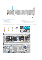
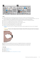
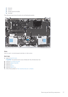
Steps 1. Remove the screw (M1.6x2.3) that secures the wireless-module bracket to the system board. 2. Lift the wireless-module bracket off the system board. 3. Remove the screw (M1.6x2.8) that secures the I/O daughter-board cable to the system board. 4. Remove the system-board interposer board off the system board. CAUTION: The pins on the interposer board are fragile. Hold and lift the interposer board from the edges or the sides. 5. Disconnect the wireless-module cables from the wireless module. 6. Lift the latch of fan cable connector, use the pull tab of the fan cable to disconnect it from the system board. 7. Lift the latch of the touch-panel connector and use the pull tab of the cable to disconnect the capacitive touch-panel cable. 8. Pry up the I/O daughter-board power cable connector from the edge that is marked white. 9. Slide the I/O daughter-board power cable connector out to disconnect the I/O daughter-board power cable from the system board. 10. Remove the five screws (M1.6x1.5) that secure the system board to the palm-rest and keyboard assembly. 11. Hold the system board by the long edges and lift the board off the palm-rest and keyboard assembly with care. Installing the system board Prerequisites If you are replacing a component, remove the existing component before performing the installation process. About this task The following image indicates the connectors and component(s) on your system board. Removing and installing components 33
-
 1
1 -
2
-
3
-
4
-
5
-
6
-
7
-
8
-
9
-
10
-
11
-
12
-
13
-
14
-
15
-
16
-
17
-
18
-
19
-
20
-
21
-
22
-
23
-
24
-
25
-
26
-
27
-
 28
28 -
 29
29 -
 30
30 -
 31
31 -
 32
32 -
 33
33 -
 34
34 -
 35
35 -
 36
36 -
 37
37 -
 38
38 -
39
-
40
-
41
-
42
-
43
-
44
-
45
-
46
-
47
-
48
-
49
-
50
-
51
-
52
-
53
-
54
-
55
-
56
-
57
-
58
-
59
-
60
-
61
-
62
-
63
-
64
-
65
-
66
 |
 |
