Dell XPS 13 9340 Owners Manual
Dell XPS 13 9340 Manual
 |
View all Dell XPS 13 9340 manuals
Add to My Manuals
Save this manual to your list of manuals |
Dell XPS 13 9340 manual content summary:
- Dell XPS 13 9340 | Owners Manual - Page 1
XPS 13 9340 Owner's Manual Regulatory Model: P151G Regulatory Type: P151G002 February 2024 Rev. A00 - Dell XPS 13 9340 | Owners Manual - Page 2
and tells you how to avoid the problem. WARNING: A WARNING indicates a potential for property damage, personal injury, or death. © 2024 Dell Inc. or its subsidiaries. All rights reserved. Dell Technologies, Dell, and other trademarks are trademarks of Dell Inc. or its subsidiaries. Other trademarks - Dell XPS 13 9340 | Owners Manual - Page 3
of XPS 13 9340...17 Camera...18 Touchpad...19 Power adapter...19 Battery...20 Display...21 Fingerprint reader...21 Fingerprint reader...22 Sensor ...22 GPU-Integrated...22 Multiple display support matrix...23 Hardware security...23 Operating and storage environment...23 Dell support policy...24 Dell - Dell XPS 13 9340 | Owners Manual - Page 4
field service kit ...27 Transporting sensitive components...28 After working inside your computer...28 BitLocker...28 Recommended tools...28 Screw list...29 Major components of XPS 13 9340...30 Drivers and downloads...75 Chapter 7: Technology and components 76 Intel Arc Graphics...76 4 Contents - Dell XPS 13 9340 | Owners Manual - Page 5
94 Clearing BIOS (System Setup) and System passwords 95 Chapter 9: Troubleshooting...96 Handling swollen rechargeable Li-ion batteries...96 Locate the Service Tag or Express Service Code of your Dell computer 96 Dell SupportAssist Pre-boot System Performance Check diagnostics 97 Running the - Dell XPS 13 9340 | Owners Manual - Page 6
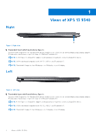
Right 1 Views of XPS 13 9340 Figure 1. Right view 1. Thunderbolt 4 port with Power Delivery (Type-C) Supports USB4, DisplayPort 1.4, Thunderbolt 4 and also enables you to connect to an external display using a display adapter. Provides data transfer rates of up to 40 Gbps - Dell XPS 13 9340 | Owners Manual - Page 7
-click. 6. Haptic touchpad Move your finger on the touchpad to move the mouse pointer. Tap to left-click and two fingers tap to right-click. 7. Service LED Views of XPS 13 9340 7 - Dell XPS 13 9340 | Owners Manual - Page 8
LED is used for troubleshooting with a Dell service representative. The LED emits amber or white light. Display Figure 4. Display view 1. Infrared emitter Emits infrared light, The infrared emitter is not available if the camera is not included in the configuration ordered. 8 Views of XPS 13 9340 - Dell XPS 13 9340 | Owners Manual - Page 9
your computer and access warranty information. 4. Right speaker Provides audio output. Service Tag The service tag is a unique alphanumeric identifier that allows Dell service technicians to identify the hardware components in your computer and access warranty information. Views of XPS 13 9340 9 - Dell XPS 13 9340 | Owners Manual - Page 10
Figure 6. Service tag location Battery charge and status light The following table lists the battery charge and status light behavior of your XPS 13 9340. Table 1. Battery charge and status light behavior Power Source LED Behavior AC Adapter Off AC Adapter Solid White Battery Off Battery - Dell XPS 13 9340 | Owners Manual - Page 11
at www.dell.com/support. For Windows: Follow the on-screen instructions to complete the setup. When setting up, Dell Technologies recommends the Support and Protection screen, enter your contact details. 3. Locate and use Dell apps from the Windows Start menu-Recommended. Set up your XPS 13 9340 11 - Dell XPS 13 9340 | Owners Manual - Page 12
hardware failures. For more information, see SupportAssist for Home PCs User's Guide at www.dell.com/ support/home/product-support/product/dell-supportassist-pcs-tablets/docs. NOTE: In SupportAssist, click the warranty expiry date to renew or upgrade your warranty. 12 Set up your XPS 13 9340 - Dell XPS 13 9340 | Owners Manual - Page 13
of the processors that are supported for your XPS 13 9340. Table 4. Processor Description Processor type Option one Intel Core Ultra 5 125H Option two Intel Core Ultra 7 155H Option three Intel Core Ultra 7 165H Processor wattage 28 W 28 W 28 W Processor core count 14 16 16 Processor - Dell XPS 13 9340 | Owners Manual - Page 14
Chipset The following table lists the details of the chipset that is supported for your XPS 13 9340. Table 5. Chipset Description Chipset Values Integrated in the processor Processor Intel Core Ultra 5/7 DRAM bus width 128-bit Flash EPROM 64 MB PCIe bus Up to Gen4 Operating system Your - Dell XPS 13 9340 | Owners Manual - Page 15
Knowledge Base Resource at www.dell.com/support. Wireless module The following table lists the Wireless Local Area Network (WLAN) module that is supported on your XPS 13 9340. Table 9. Wireless module specifications Description Model number Values Intel BE200 Specifications of XPS 13 9340 15 - Dell XPS 13 9340 | Owners Manual - Page 16
. Audio The following table lists the audio specifications of your XPS 13 9340. Table 10. Audio specifications Description Audio controller Values USB Type-C digital audio/SoundWire codecs Stereo conversion Supported Internal audio interface SoundWire interface External audio interface Two - Dell XPS 13 9340 | Owners Manual - Page 17
This section lists the storage options on your XPS 13 9340. Your XPS 13 9340 supports one M.2 2230 or M.2 2280 solid-state changing Function Key Behavior in BIOS setup program. Keyboard shortcuts of XPS 13 9340 NOTE: Keyboard characters may differ depending on the keyboard language configuration. - Dell XPS 13 9340 | Owners Manual - Page 18
For more information about Copilot in Windows, search in the Knowledge Base Resource at www.dell.com/support. fn fn + B fn + S fn + R fn + ctrl + B Camera The following table lists the camera specifications of your XPS 13 9340. Table 14. Camera specifications Description Number of cameras - Dell XPS 13 9340 | Owners Manual - Page 19
about touchpad gestures available on Windows, see the Microsoft Knowledge Base article at support.microsoft.com. Power adapter The following table lists the power adapter specifications of your XPS 13 9340. Table 16. Power adapter specifications Description Type Values 60 W AC adapter, USB Type - Dell XPS 13 9340 | Owners Manual - Page 20
: Dell Technologies recommends that you charge the battery regularly for optimal power consumption. If your battery charge is completely depleted, connect the power adapter, turn on your computer, and then restart your computer to reduce the power consumption. 20 Specifications of XPS 13 9340 - Dell XPS 13 9340 | Owners Manual - Page 21
The following table lists the display specifications of your XPS 13 9340. Table 18. Display specifications Description Option one Option The following table lists the fingerprint-reader specifications of your XPS 13 9340. NOTE: The fingerprint reader is on the power button. Specifications of - Dell XPS 13 9340 | Owners Manual - Page 22
GPU-Integrated The following table lists the specifications of the integrated Graphics Processing Unit (GPU) supported by your XPS 13 9340. Table 22. GPU-Integrated Controller Memory size Processor Intel Arc Graphics Shared system memory Intel Core Ultra 5/7 22 Specifications of XPS 13 9340 - Dell XPS 13 9340 | Owners Manual - Page 23
Link WLAN and a vPro compatible processor) Intel Platform Trust Technology Support for Absolute module interface and external SmartCard Reader Operating and storage environment This table lists the operating and storage specifications of your XPS 13 9340. Airborne contaminant level: G1 as defined - Dell XPS 13 9340 | Owners Manual - Page 24
using a 2 ms half-sine pulse. Dell support policy For information about Dell support policy, search in the Knowledge Base Resource at www.dell.com/support. Dell low blue light display WARNING: Prolonged exposure Take an extended break for 20 minutes every two hours. 24 Specifications of XPS 13 9340 - Dell XPS 13 9340 | Owners Manual - Page 25
and the contacts. CAUTION: You should only perform troubleshooting and repairs as authorized or directed by the Dell technical assistance team. Damage due to servicing that is not authorized by Dell is not covered by your warranty. See the safety instructions that is shipped with the product or at - Dell XPS 13 9340 | Owners Manual - Page 26
Service Mode, or the computer does not support Service 3 seconds or until the Dell logo appears on the screen. Service Mode, skip this process. Safety precautions The safety precautions chapter details the primary steps to be taken before performing any disassembly instructions problems or - Dell XPS 13 9340 | Owners Manual - Page 27
higher than in previous Dell products. For this reason The more difficult type of damage to recognize and troubleshoot is the intermittent (also called latent or "walking mat, and the hardware is known as bonding. Use only Field Service kits with a wrist strap, mat, and bonding wire. Never use - Dell XPS 13 9340 | Owners Manual - Page 28
for safe transport. ESD protection summary It is recommended to use the traditional wired ESD grounding wrist strap and protective anti-static mat always when servicing Dell products. In addition, it is critical to keep sensitive parts separate from all insulator parts while performing - Dell XPS 13 9340 | Owners Manual - Page 29
Screw list NOTE: When removing screws from a component, it is recommended to note the screw type, the quantity of screws, and then place them in a screw storage box. This is to ensure that the correct number of screws and correct screw type is restored when the component is replaced. NOTE: Some - Dell XPS 13 9340 | Owners Manual - Page 30
Major components of XPS 13 9340 The following image shows the major components of XPS 13 9340. Figure 12. Major components of your computer 1. Base cover 2. System board 3. Heat sink 4. Display assembly-cable bracket 5. M.2 solid-state drive thermal plate 6. M.2 solid-state drive 7. - Dell XPS 13 9340 | Owners Manual - Page 31
11. Battery-connector bracket 12. Wireless-module bracket 13. Keyboard 14. Right fan 15. Left fan 16. Right speaker 17. Left speaker NOTE: Dell provides a list of components and their part numbers for the original computer configuration purchased. These parts are available according to warranty - Dell XPS 13 9340 | Owners Manual - Page 32
only. CAUTION: To avoid any potential damage to the component or loss of data, ensure that an authorized service technician replaces the Field Replaceable Units (FRUs). CAUTION: Dell Technologies recommends that this set of repairs, if needed, to be conducted by trained technical repair specialists - Dell XPS 13 9340 | Owners Manual - Page 33
Figure 13. Removing the base cover Removing and installing Field Replaceable Units (FRUs) 33 - Dell XPS 13 9340 | Owners Manual - Page 34
Figure 14. Removing the base cover Figure 15. Removing the base cover Steps 1. Remove the six screws (M2x3, T5) that secure the base cover to the palm-rest and keyboard assembly. 34 Removing and installing Field Replaceable Units (FRUs) - Dell XPS 13 9340 | Owners Manual - Page 35
NOTE: A Torx #5 (T5) screwdriver is necessary to remove the six screws (M2x3, Torx 5). 2. Place your thumbs and fingers into the recess at the top edge of the base cover. 3. Use both thumbs to pry the base cover in order to release it from the palm-rest and keyboard assembly. NOTE: Do not pull on or - Dell XPS 13 9340 | Owners Manual - Page 36
Figure 17. Installing the base cover Steps 1. Place and snap the base cover into place on the palm-rest and keyboard assembly. NOTE: Align the screw holes on the base cover with the screw holes on the palm-rest and keyboard assembly before applying slight pressure to the base cover. 2. Replace the - Dell XPS 13 9340 | Owners Manual - Page 37
on or against the battery. ● Ensure any screws during the servicing of this product are not lost or misplaced, to prevent accidental contact Dell technical support for assistance. See www.dell.com/contactdell. ● Always purchase genuine batteries from www.dell.com or authorized Dell partners and - Dell XPS 13 9340 | Owners Manual - Page 38
Figure 18. Removing the battery 38 Removing and installing Field Replaceable Units (FRUs) - Dell XPS 13 9340 | Owners Manual - Page 39
Figure 19. Removing the battery Steps 1. Loosen the captive screw (M1.6x2) that secures the battery-connector bracket to the system board. 2. Unhook and lift the battery-connector bracket off the system board. Figure 20. Battery-connector bracket 3. Use the pull tab on the battery power cable to - Dell XPS 13 9340 | Owners Manual - Page 40
Figure 21. Lift the battery at an angle less than 30 degrees 6. Slide the battery towards the back and lift the battery off the palm-rest and keyboard assembly. Installing the battery Prerequisites If you are replacing a component, remove the existing component before performing the installation - Dell XPS 13 9340 | Owners Manual - Page 41
Figure 22. Installing the battery Removing and installing Field Replaceable Units (FRUs) 41 - Dell XPS 13 9340 | Owners Manual - Page 42
Figure 23. Installing the battery Steps 1. Align the edge of the battery at an angle so that the cutouts on the battery fit into the hooks on the palm-rest and keyboard assembly. Align the two screw holes on the battery with the screw holes on the palm-rest and keyboard assembly as well. 2. Lower - Dell XPS 13 9340 | Owners Manual - Page 43
procedure in Before working inside your computer. 2. Remove the base cover. About this task NOTE: Depending on the configuration ordered, your computer may support an M.2 2230 solid-state drive or an M.2 2280 solid-state drive. NOTE: This procedure applies only to computers shipped with an M.2 2230 - Dell XPS 13 9340 | Owners Manual - Page 44
procedure in Before working inside your computer. 2. Remove the base cover. About this task NOTE: Depending on the configuration ordered, your computer may support an M.2 2230 solid-state drive or an M.2 2280 solid-state drive. NOTE: This procedure applies only to computers shipped with an M.2 2280 - Dell XPS 13 9340 | Owners Manual - Page 45
component, remove the existing component before performing the installation process. About this task NOTE: Depending on the configuration ordered, your computer may support an M.2 2230 solid-state drive or an M.2 2280 solid-state drive. NOTE: This procedure applies only to computers shipped with an - Dell XPS 13 9340 | Owners Manual - Page 46
Figure 27. Installing the M.2 2280 solid-state drive Steps 1. Align the notch on the M.2 2280 solid-state drive with the tab on the solid-state drive slot. 2. Slide the M.2 2280 solid-state drive into the solid-state drive slot. 3. Insert the tab of the M.2 solid-state drive shield into the peg on - Dell XPS 13 9340 | Owners Manual - Page 47
Figure 28. Removing the left fan Figure 29. Removing the right fan Steps 1. Lift the latch of left-fan cable connector, use the pull tab of the left-fan cable to disconnect it from the system board. 2. Remove the two screws (M1.6x2.5) that secure the left fan to the system board. 3. Lift the left - Dell XPS 13 9340 | Owners Manual - Page 48
Installing the fans Prerequisites If you are replacing a component, remove the existing component before performing the installation process. About this task The following image(s) indicate the location of the fans and provides a visual representation of the installation procedure. Figure 30. - Dell XPS 13 9340 | Owners Manual - Page 49
Steps 1. Align the screw holes of the left fan with the screw holes of the system board. 2. Replace the two screws (M1.6x2.5) that secure the left fan to the system board. 3. Connect the left fan cable to the system board. 4. Align the screw holes of the right fan with the screw holes of the system - Dell XPS 13 9340 | Owners Manual - Page 50
Steps 1. In reverse sequential order (4>3>2>1) as indicated on the heat sink, loosen the four captive screws that secure the heat sink to the system board. 2. Lift the heat sink off the system board. Installing the heat sink Prerequisites If you are replacing a component, remove the existing - Dell XPS 13 9340 | Owners Manual - Page 51
Display assembly Removing the display assembly Prerequisites 1. Follow the procedure in Before working inside your computer. 2. Remove the base cover. About this task The following images indicate the location of the display assembly and provide a visual representation of the removal procedure. - Dell XPS 13 9340 | Owners Manual - Page 52
Figure 34. Removing the display assembly Steps 1. Loosen the three captive screws (M1.6x2) that secure the display-assembly cable bracket to the system board. 2. Lift the display-assembly cable bracket off the system board. 3. Disconnect the camera cable and the display cable from the system board. - Dell XPS 13 9340 | Owners Manual - Page 53
8. Lift the display assembly off the palm-rest and keyboard assembly. 9. After performing all the above steps, you are left with the display assembly. Installing the display assembly Prerequisites If you are replacing a component, remove the existing component before performing the installation - Dell XPS 13 9340 | Owners Manual - Page 54
Figure 35. Installing the display assembly Steps 1. Open the display assembly to a 90-degree angle and place the computer on the edge of a flat surface. 2. Place the palm-rest and keyboard assembly at the edge of a flat table. 3. Open the hinges of the display assembly to a 90-degree angle. 4. Align - Dell XPS 13 9340 | Owners Manual - Page 55
-assembly cable connector 5. Left-speaker cable connector 7. Haptic-module cable connector 9. Battery cable connector 11. Right-fan cable connector 13. Power-button and fingerprint-reader cable connector 2. Camera-assembly cable connector 4. Capacitive touch-panel cable connector 6. Left-fan cable - Dell XPS 13 9340 | Owners Manual - Page 56
Figure 37. Removing the system board 56 Removing and installing Field Replaceable Units (FRUs) - Dell XPS 13 9340 | Owners Manual - Page 57
Figure 38. Removing the system board Steps NOTE: When removing the system board, open the display assembly to a 90-degree angle and then place the computer on the edge of a flat surface. Ensure to maintain the angle throughout the removal process to minimize the risk of damaging the thin display - Dell XPS 13 9340 | Owners Manual - Page 58
-speaker cable. 12. Lift the latch of the power-button connector and use the pull tab of the cable to disconnect the power-button cable. 13. Remove the four screws (M1.6x3) that secure the system board to the palm-rest and keyboard assembly. 14. Remove the seven screws (M1.6x2 - Dell XPS 13 9340 | Owners Manual - Page 59
-assembly cable connector 5. Left-speaker cable connector 7. Haptic-module cable connector 9. Battery cable connector 11. Right-fan cable connector 13. Power-button and fingerprint-reader cable connector 2. Camera-assembly cable connector 4. Capacitive touch-panel cable connector 6. Left-fan cable - Dell XPS 13 9340 | Owners Manual - Page 60
Figure 41. Installing the system board 60 Removing and installing Field Replaceable Units (FRUs) - Dell XPS 13 9340 | Owners Manual - Page 61
Figure 42. Installing the system board Steps NOTE: When installing the system board, open the display assembly to a 90-degree angle and then place the computer on the edge of a flat surface. Ensure to maintain the angle throughout the installation process to minimize the risk of damaging the thin - Dell XPS 13 9340 | Owners Manual - Page 62
connector. 11. Connect the camera cable and the display cable to the system board. 12. Connect the wireless-module cables from the wireless module. 13. Replace the display-assembly cable bracket on the system board. 14. Tighten the three captive screws (M1.6x2) that secure the display-assembly cable - Dell XPS 13 9340 | Owners Manual - Page 63
3. Install the battery. 4. Install the M.2 2230 solid-state drive or M.2 2280 solid-state drive from M.2 slot, whichever is applicable. 5. Install the base cover. 6. Follow the procedure in After working inside your computer. Power button with fingerprint reader Removing the power button with - Dell XPS 13 9340 | Owners Manual - Page 64
Figure 45. Opening the display assembly to a 90-degree angle 1. Open the display assembly to a 90-degree angle and place the computer on the edge of a flat surface. 2. Remove the four screws (M1.4x2) that secure the power-button bracket to the palm-rest and keyboard assembly. 3. Lift the power- - Dell XPS 13 9340 | Owners Manual - Page 65
Figure 46. Installing the power button with fingerprint reader Steps NOTE: When installing the power button with fingerprint reader, open the display assembly to a 90-degree angle and then place the computer on the edge of a flat surface. Ensure to maintain the angle throughout the installation - Dell XPS 13 9340 | Owners Manual - Page 66
Figure 47. Opening the display assembly to a 90-degree angle 1. Open the display assembly to a 90-degree angle and place the computer on the edge of a flat surface. 2. Thread the power-button cable through the opening on the palm-rest and keyboard assembly. 3. Place the power button with fingerprint - Dell XPS 13 9340 | Owners Manual - Page 67
3. Remove the battery. 4. Remove the system board. NOTE: The system board can be removed with the following components attached: ● heat sink ● fans ● solid-state drive 5. Remove the power button with fingerprint reader. About this task The following images indicate the location of the keyboard and - Dell XPS 13 9340 | Owners Manual - Page 68
Figure 49. Removing the keyboard Steps NOTE: When removing the keyboard, open the display assembly to a 90-degree angle and then place the computer on the edge of a flat surface. Ensure to maintain the angle throughout the removal process to minimize the risk of damaging the thin display panel when - Dell XPS 13 9340 | Owners Manual - Page 69
Figure 50. Opening the display assembly to a 90-degree angle 1. Remove the 17 screws (M1.4x1.2) that secure the keyboard to the palm-rest assembly. 2. Remove the seven screws (M1.6x2) that secure the keyboard to the palm-rest assembly. 3. Lift the latch of the keyboard-backlight connector and use - Dell XPS 13 9340 | Owners Manual - Page 70
Figure 51. Installing the keyboard Figure 52. Installing the keyboard 70 Removing and installing Field Replaceable Units (FRUs) - Dell XPS 13 9340 | Owners Manual - Page 71
Steps NOTE: When installing the keyboard, open the display assembly to a 90-degree angle and then place the computer on the edge of a flat surface. Ensure to maintain the angle throughout the installation process to minimize the risk of damaging the thin display panel when applying torque to install - Dell XPS 13 9340 | Owners Manual - Page 72
Palm-rest assembly Removing the palm-rest assembly Prerequisites 1. Follow the procedure in Before working inside your computer. 2. Remove the base cover. 3. Remove the battery. 4. Remove the display assembly. 5. Remove the system board. NOTE: The system board can be removed with the following - Dell XPS 13 9340 | Owners Manual - Page 73
Installing the palm-rest assembly Prerequisites If you are replacing a component, remove the existing component before performing the installation process. About this task NOTE: The replacement palm-rest assembly comes preassembled with the following components that include the following: ● palm - Dell XPS 13 9340 | Owners Manual - Page 74
5. Install the battery. 6. Install the base cover. 7. Follow the procedure in After working inside your computer. 74 Removing and installing Field Replaceable Units (FRUs) - Dell XPS 13 9340 | Owners Manual - Page 75
supported operating systems along with instructions on how to install the drivers. Operating system Your XPS 13 9340 supports the following operating systems: ● Windows 11 Pro ● Windows 11 Pro National Education ● Windows 11 Home ● Ubuntu Linux 22.04 LTS Drivers and downloads When troubleshooting - Dell XPS 13 9340 | Owners Manual - Page 76
Instructions that are provided in the following section are applicable on computers that are shipped with the Windows operating system. Windows is factory-installed with this computer. Intel Arc Graphics The following table lists the Intel display support Values Integrated graphics NOTE: Intel Arc - Dell XPS 13 9340 | Owners Manual - Page 77
8 BIOS Setup CAUTION: Unless you are an expert computer user, do not change the settings in the BIOS Setup. Certain changes can make your computer work incorrectly. NOTE: Depending on the computer and its installed devices, the items that are listed in this section may or may not be displayed. - Dell XPS 13 9340 | Owners Manual - Page 78
setup options-Overview menu Overview XPS 13 9340 BIOS Version Displays the BIOS version number. Service Tag Displays the Service Tag of the computer. Asset Type Maximum Clock Speed Minimum Clock Speed Current Clock Speed Core Count Processor ID Processor L2 Cache Displays the primary battery - Dell XPS 13 9340 | Owners Manual - Page 79
Cache size. Microcode Version Displays the microcode version. Intel Hyper-Threading Capable Displays whether the processor is Hyper- Secure Boot can be enabled in BIOS setup or using management interfaces like Dell Command|Configure, but can only be disabled from BIOS setup. Enables the - Dell XPS 13 9340 | Owners Manual - Page 80
properly, and the computer could become unrecoverable. By default, the Enable Microsoft UEFI CA option is enabled. For additional security, Dell Technologies recommends keeping the Microsoft UEFI CA option enabled to ensure the broadest compatibility with devices and operating systems. Expert Key - Dell XPS 13 9340 | Owners Manual - Page 81
used during BIOS Preboot. By default, the Enable Thunderbolt Boot Support option is disabled. Enable Thunderbolt (and PCIe behind TBT) Type-C Dock Type-C Dock Override Enables or disable to use connected Type-C Dell Dock to provide data stream with external USB ports disabled. When Type-C Dock - Dell XPS 13 9340 | Owners Manual - Page 82
mode of the integrated SATA hard drive controller. By default, the RAID ON option is selected. The storage device is configured to support RAID functions. Storage Interface Port Enablement Displays the information of various onboard drives. Enables or disables the M.2 PCIe SSD option. By default - Dell XPS 13 9340 | Owners Manual - Page 83
, noise, and temperature. USB Wake Support Wake on Dell USB-C Dock When enabled, connecting a Dell USB-C Dock wakes the computer from is disabled. NOTE: When enabled, the computer does not go to Sleep, Intel Rapid Start is disabled automatically, and the operating system power option is blank if - Dell XPS 13 9340 | Owners Manual - Page 84
Open option is enabled. Intel Speed Shift Technology Enables or disables the Intel Speed Shift Technology support. When enabled, the operating By default, the SHA-256 option is enabled. For additional security, Dell Technologies recommends keeping the SHA-256 option enabled. Clear When enabled, - Dell XPS 13 9340 | Owners Manual - Page 85
apply to computers with a discrete Trusted Platform Module (TPM). PTT On Enables or disables the Intel PTT option. By default, the PTT On option is enabled. For additional security, Dell Technologies recommends keeping the PTT On option enabled. Physical Presence Interface (PPI) Bypass for Clear - Dell XPS 13 9340 | Owners Manual - Page 86
of functionality with some legacy tools and applications. Absolute Absolute Software provides various cyber security solutions, some requiring software preloaded on Dell computers and integrated into the BIOS. To use these features, you must enable the Absolute BIOS setting and contact Absolute - Dell XPS 13 9340 | Owners Manual - Page 87
an end user to provide their own password. By default, the Allow Non-Admin Password Changes option is enabled. For additional security, Dell Technologies recommends keeping the Allow NonAdmin Password Changes option disabled. Admin Setup Lockout The Admin Setup Lockout option prevents an end user - Dell XPS 13 9340 | Owners Manual - Page 88
the value specified by the Auto operating system Recovery Threshold setup option and the local Service operating system does not boot or is not installed. By default, the BIOSConnect option is enabled. Dell Auto OS Recovery Threshold Allows you to control the automatic boot flow for SupportAssist - Dell XPS 13 9340 | Owners Manual - Page 89
. By default, the Device Configuration HotKey Access option is enabled. NOTE: This setting controls only the Intel RAID (CTRL+I), MEBX (CTRL+P), and LSI RAID (CTRL+C) Option ROMs. Other preboot Option ROMs, which support entry using a key sequence, are not affected by this setting. BIOS Setup 89 - Dell XPS 13 9340 | Owners Manual - Page 90
Life. By default, the Early Keyboard Backlight option is enabled. Table 42. System setup options-Virtualization menu Virtualization Support Intel Virtualization Technology Enable Intel Virtualization Technology (VT) When enabled, the computer can run a Virtual Machine Monitor (VMM). By default, the - Dell XPS 13 9340 | Owners Manual - Page 91
Dell Technologies recommends keeping the Intel Trusted Execution Technology (TXT) option enabled. DMA Protection Enable Pre-Boot DMA Support Allows menu Performance Multi-Core Support Active Multiple Performance Cores (PCores) Select Enables to change the number of CPU cores available for the - Dell XPS 13 9340 | Owners Manual - Page 92
on each core. By default, the Intel Hyper-Threading Go to www.dell.com/support. 2. Click Product support. In the Search support box, enter the Service Tag of your instructions. For more information about how to update the system BIOS, search in the Knowledge Base Resource at www.dell.com/ support - Dell XPS 13 9340 | Owners Manual - Page 93
and press Enter. The BIOS Update Utility appears. 8. Follow the on-screen instructions to complete the BIOS update. Updating the BIOS in Linux and Ubuntu To have to be bootable) ● BIOS executable file that you downloaded from the Dell Support website and copied to the root of the USB drive ● AC power - Dell XPS 13 9340 | Owners Manual - Page 94
System and setup password Table 45. System and setup password Password type System password Setup password Description Password that you must enter to log in to your system. Password that you must enter to access and make changes to the BIOS settings of your computer. You can create a system - Dell XPS 13 9340 | Owners Manual - Page 95
. Clearing BIOS (System Setup) and System passwords About this task To clear the system or BIOS passwords, contact Dell technical support as described at www.dell.com/contactdell. NOTE: For information about how to reset Windows or application passwords, see the documentation accompanying Windows or - Dell XPS 13 9340 | Owners Manual - Page 96
Service Code. To view relevant support resources for your Dell computer, we recommend entering the Service Tag or Express Service Code at www.dell.com/support. For more information about how to find the Service Tag for your computer, see Locate the Service Tag on your computer. 96 Troubleshooting - Dell XPS 13 9340 | Owners Manual - Page 97
codes are displayed. Note the error code and validation number and contact Dell. Built-in self-test (BIST) M-BIST M-BIST (Built In Embedded Controller (EC) failures. NOTE: M-BIST can be manually initiated before Power On Self-Test (POST). How to run problem with the system board. Troubleshooting 97 - Dell XPS 13 9340 | Owners Manual - Page 98
Pattern Amber 2 White 1 Possible Problem CPU Failure 2 8 LCD Power problem with the LCD (screen) of the Dell invoke the LCD BIST Test 1. Power off the Dell laptop. 2. Disconnect any peripherals that are connected to computer shuts down. NOTE: Dell SupportAssist Preboot diagnostics upon launch - Dell XPS 13 9340 | Owners Manual - Page 99
Dell Support website to troubleshoot and Guide at www.dell.com/serviceabilitytools. Click SupportAssist and then, click SupportAssist OS Recovery. Real Time Clock-RTC reset The Real Time Clock (RTC) reset function allows you or the service technician to recover the recently launched model Dell XPS - Dell XPS 13 9340 | Owners Manual - Page 100
troubleshoot and fix problems that may occur with Windows. Dell proposes multiple options for recovering the Windows operating system on your Dell computer. For more information, see Dell provides the instructions on how to conduct a Wi-Fi power cycle: NOTE: Some Internet Service Providers (ISPs - Dell XPS 13 9340 | Owners Manual - Page 101
power adapter to your computer. 9. Turn on your computer. NOTE: For more information about performing a hard reset, search in the Knowledge Base Resource at www.dell.com/ support. Troubleshooting 101 - Dell XPS 13 9340 | Owners Manual - Page 102
your computer through videos, manuals, and documents. Your Dell computer is uniquely identified by a Service Tag or Express Service Code. To view relevant support resources for your Dell computer, enter the Service Tag or Express Service Code at www.dell.com/support. For more information about
-
 1
1 -
 2
2 -
 3
3 -
 4
4 -
 5
5 -
 6
6 -
 7
7 -
8
-
9
-
10
-
11
-
12
-
13
-
14
-
15
-
16
-
17
-
18
-
19
-
20
-
21
-
22
-
23
-
24
-
25
-
26
-
27
-
28
-
29
-
30
-
31
-
32
-
33
-
34
-
35
-
36
-
37
-
38
-
39
-
40
-
41
-
42
-
43
-
44
-
45
-
46
-
47
-
48
-
49
-
50
-
51
-
52
-
53
-
54
-
55
-
56
-
57
-
58
-
59
-
60
-
61
-
62
-
63
-
64
-
65
-
66
-
67
-
68
-
69
-
70
-
71
-
72
-
73
-
74
-
75
-
76
-
77
-
78
-
79
-
80
-
81
-
82
-
83
-
84
-
85
-
86
-
87
-
88
-
89
-
90
-
91
-
92
-
93
-
94
-
95
-
96
-
97
-
98
-
99
-
100
-
101
-
102
 |
 |

XPS 13 9340
Owner's Manual
Regulatory Model: P151G
Regulatory Type: P151G002
February 2024
Rev. A00