Dell XPS 13 9340 Owners Manual - Page 71
Opening the display assembly to a 90-degree angle
 |
View all Dell XPS 13 9340 manuals
Add to My Manuals
Save this manual to your list of manuals |
Page 71 highlights
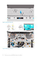
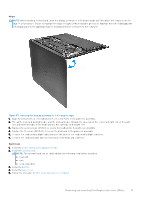
Steps NOTE: When installing the keyboard, open the display assembly to a 90-degree angle and then place the computer on the edge of a flat surface. Ensure to maintain the angle throughout the installation process to minimize the risk of damaging the thin display panel when applying torque to install and remove screws from the computer. Figure 53. Opening the display assembly to a 90-degree angle 1. Align the screw holes of the keyboard with the screw holes of the palm-rest assembly. 2. Thread the keyboard-backlight cable and the keyboard cable through the openings at the center and right side of the palm rest and insert the tabs on the keyboard into the openings on the palm rest. 3. Replace the seven screws (M1.6x2) to secure the keyboard to the palm-rest assembly. 4. Replace the 17 screws (M1.4x1.2) to secure the keyboard to the palm-rest assembly. 5. Connect the keyboard-backlight cable and close the latch of the keyboard-backlight connector. 6. Connect the keyboard cable and close the latch of the keyboard connector. Next steps 1. Install the power button with fingerprint reader. 2. Install the system board. NOTE: The system board can be replaced with the following components attached: ● heat sink ● fans ● solid-state drive 3. Install the battery. 4. Install the base cover. 5. Follow the procedure in After working inside your computer. Removing and installing Field Replaceable Units (FRUs) 71
-
 1
1 -
2
-
3
-
4
-
5
-
6
-
7
-
8
-
9
-
10
-
11
-
12
-
13
-
14
-
15
-
16
-
17
-
18
-
19
-
20
-
21
-
22
-
23
-
24
-
25
-
26
-
27
-
28
-
29
-
30
-
31
-
32
-
33
-
34
-
35
-
36
-
37
-
38
-
39
-
40
-
41
-
42
-
43
-
44
-
45
-
46
-
47
-
48
-
49
-
50
-
51
-
52
-
53
-
54
-
55
-
56
-
57
-
58
-
59
-
60
-
61
-
62
-
63
-
64
-
65
-
 66
66 -
 67
67 -
 68
68 -
 69
69 -
 70
70 -
 71
71 -
 72
72 -
 73
73 -
 74
74 -
 75
75 -
 76
76 -
77
-
78
-
79
-
80
-
81
-
82
-
83
-
84
-
85
-
86
-
87
-
88
-
89
-
90
-
91
-
92
-
93
-
94
-
95
-
96
-
97
-
98
-
99
-
100
-
101
-
102
 |
 |
