Dell XPS 13 9340 Owners Manual - Page 72
Palm-rest assembly, Removing the palm-rest assembly
 |
View all Dell XPS 13 9340 manuals
Add to My Manuals
Save this manual to your list of manuals |
Page 72 highlights
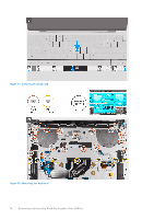
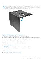
Palm-rest assembly Removing the palm-rest assembly Prerequisites 1. Follow the procedure in Before working inside your computer. 2. Remove the base cover. 3. Remove the battery. 4. Remove the display assembly. 5. Remove the system board. NOTE: The system board can be removed with the following components attached: ● heat sink ● fans ● solid-state drive 6. Remove the power button with fingerprint reader. 7. Remove the keyboard. About this task The following images indicate the location of the palm-rest assembly and provide a visual representation of the removal procedure. Figure 54. Removing the palm-rest assembly Steps After performing the steps in the pre-requisites, you are left with the palm-rest assembly. 72 Removing and installing Field Replaceable Units (FRUs)
-
 1
1 -
2
-
3
-
4
-
5
-
6
-
7
-
8
-
9
-
10
-
11
-
12
-
13
-
14
-
15
-
16
-
17
-
18
-
19
-
20
-
21
-
22
-
23
-
24
-
25
-
26
-
27
-
28
-
29
-
30
-
31
-
32
-
33
-
34
-
35
-
36
-
37
-
38
-
39
-
40
-
41
-
42
-
43
-
44
-
45
-
46
-
47
-
48
-
49
-
50
-
51
-
52
-
53
-
54
-
55
-
56
-
57
-
58
-
59
-
60
-
61
-
62
-
63
-
64
-
65
-
66
-
 67
67 -
 68
68 -
 69
69 -
 70
70 -
 71
71 -
 72
72 -
 73
73 -
 74
74 -
 75
75 -
 76
76 -
 77
77 -
78
-
79
-
80
-
81
-
82
-
83
-
84
-
85
-
86
-
87
-
88
-
89
-
90
-
91
-
92
-
93
-
94
-
95
-
96
-
97
-
98
-
99
-
100
-
101
-
102
 |
 |
