Dewalt DXGNR8000 Instruction Manual - Page 10
Battery Replacement/Connection, Emissions Information, Install Frame Foot and Rubber Bumpers
 |
View all Dewalt DXGNR8000 manuals
Add to My Manuals
Save this manual to your list of manuals |
Page 10 highlights
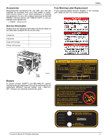
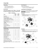
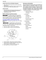
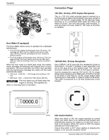
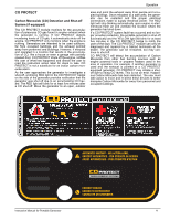
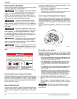
Assembly Install Frame Foot and Rubber Bumpers 1. Slide rubber foot (E) through frame foot (B). Install locking flange nuts (K). 2. Slide M8 bolt (J) through holes in frame rail. Slide frame foot (B) onto M8 bolts. Install locking flange nuts (K). Install Handle 1. Slide M8 carriage bolt (H) through handle bracket and handle assembly (C) by first inserting the bolt through the square hole in the handle assembly (C). 2. Install M8 flange nut (K). Battery Replacement/Connection NOTICE: The battery shipped with the generator has been fully charged. A battery may lose some charge when not in use for prolonged periods of time. If battery is unable to crank engine, plug in the 12V charger included in the accessory box (see Charging the Battery (electric start units only) IMPORTANT: Running the generator does not charge battery. WARNING Accidental Start-up. Disconnect the negative battery cable, then the posi- tive battery cable when working on unit. Failure to do so could result in death or serious injury. 1. Disconnect negative (-) battery terminal FIRST (A). 2. Disconnect positive (+) battery terminal SECOND (B). Emissions Information The Environmental Protection Agency and California Air Resource Board "for generators certified to CA standards" requires that this generator comply with exhaust and evaporative emission standards. Locate the emissions compliance decal on the engine to determine what standards the generator meets. This generator is certified to operate on gasoline. The emission control system includes the following components (if equipped): • Air Induction System - Intake Pipe / Manifold - Air Cleaner • Fuel System - Carburetor - Fuel Tank / Cap - Fuel Lines - Evaporative Vent Lines - Carbon Canister • Ignition System - Spark Plug - Ignition Module • Exhaust System - Exhaust Manifold - Muffler - Pulsed Air Valve - Catalyst B 000224 A 3. Install new battery. Install hold down bracket and tighten. 4. Connect positive (+) battery terminal (B) FIRST (B). Slide rubber boot over connection hardware. 5. Connect negative (-) battery terminal (A) SECOND. 6. Slide rubber boot over connection hardware. 8 Instruction Manual for Portable Generator
-
 1
1 -
2
-
3
-
4
-
 5
5 -
 6
6 -
 7
7 -
 8
8 -
 9
9 -
 10
10 -
 11
11 -
 12
12 -
 13
13 -
 14
14 -
 15
15 -
16
-
17
-
18
-
19
-
20
-
21
-
22
-
23
-
24
-
25
-
26
-
27
-
28
-
29
-
30
-
31
-
32
-
33
-
34
-
35
-
36
-
37
-
38
-
39
-
40
-
41
-
42
-
43
-
44
-
45
-
46
-
47
-
48
-
49
-
50
-
51
-
52
-
53
-
54
-
55
-
56
-
57
-
58
-
59
-
60
-
61
-
62
-
63
-
64
-
65
-
66
-
67
-
68
-
69
-
70
-
71
-
72
-
73
-
74
-
75
-
76
-
77
-
78
-
79
-
80
 |
 |