Dewalt DXGNR8000 Instruction Manual - Page 21
Battery Replacement/Connection (if equipped), Valve Clearance, NOTICE, WARNING
 |
View all Dewalt DXGNR8000 manuals
Add to My Manuals
Save this manual to your list of manuals |
Page 21 highlights
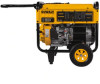
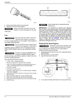
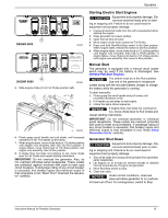
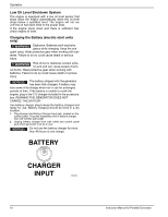
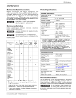
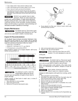
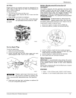
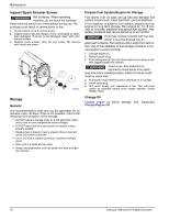
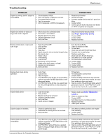
Maintenance Air Filter Engine will not run properly and may be damaged if run with a dirty air filter. Service air filter more frequently in dirty or dusty conditions. To service air filter: 1. Turn knob (A) and remove air filter cover. 2. Wash in soapy water. Squeeze filter dry in clean cloth (DO NOT TWIST). 3. Clean air filter cover before re-installing it. NOTICE: 431-6871. To order a new air filter, contact the nearest authorized service center at 1-888- Battery Replacement/Connection (if equipped) The battery shipped with the generator has been fully charged. A battery may lose some charge when not in use for prolonged periods of time. If battery is unable to crank engine, plug in the 12V charger included in the accessory box (see the Charging a Battery section). IMPORTANT: RUNNING THE GENERATOR DOES NOT CHARGE BATTERY. WARNING Accidental Start-up. Disconnect the negative battery cable, then the posi- tive battery cable when working on unit. Failure to do so could result in death or serious injury. 1. Disconnect negative (-) battery terminal FIRST (A). 2. Disconnect positive (+) battery terminal SECOND (B). B 000809 A Service Spark Plug To service spark plug: 1. Clean area around spark plug. 2. Remove and inspect spark plug. 3. Inspect electrode gap with wire feeler gauge and reset spark plug gap to 0.028 - 0.031 in (0.70 - 0.80 mm). 000211 NOTICE: Replace spark plug if electrodes are pitted, burned or porcelain is cracked. Use ONLY recommended replacement plug. See Specifica- tions. 4. Install spark plug finger tight, and tighten an additional 3/8 to 1/2 turn using spark plug wrench. 000224 A 3. Install new battery. Install hold down bracket and tighten. 4. Connect positive (+) battery terminal (B) FIRST (B). Slide rubber boot over connection hardware. 5. Connect negative (-) battery terminal (A) SECOND. 6. Slide rubber boot over connection hardware. Valve Clearance IMPORTANT: If uncomfortable about doing this procedure, or the proper tools are not available, take generator to the nearest service center to have valve clearance adjusted. Check valve clearance after the first fifty-hours of operation. Adjust as necessary. 6500/8000 • Intake - 0.09 ± 0.02mm (cold), (0.004" ± 0.001" inches) • Exhaust - 0.14 ± 0.02mm (cold) (0.006" ± 0.001" inches) Instruction Manual for Portable Generator 19
-
 1
1 -
2
-
3
-
4
-
5
-
6
-
7
-
8
-
9
-
10
-
11
-
12
-
13
-
14
-
15
-
 16
16 -
 17
17 -
 18
18 -
 19
19 -
 20
20 -
 21
21 -
 22
22 -
 23
23 -
 24
24 -
 25
25 -
 26
26 -
27
-
28
-
29
-
30
-
31
-
32
-
33
-
34
-
35
-
36
-
37
-
38
-
39
-
40
-
41
-
42
-
43
-
44
-
45
-
46
-
47
-
48
-
49
-
50
-
51
-
52
-
53
-
54
-
55
-
56
-
57
-
58
-
59
-
60
-
61
-
62
-
63
-
64
-
65
-
66
-
67
-
68
-
69
-
70
-
71
-
72
-
73
-
74
-
75
-
76
-
77
-
78
-
79
-
80
 |
 |