Epson ActionNote 650 User Manual - Page 79
Installing Optional, heat spreader. Do not remove this pad. If it adheres
 |
View all Epson ActionNote 650 manuals
Add to My Manuals
Save this manual to your list of manuals |
Page 79 highlights
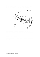
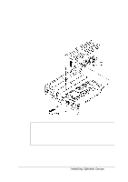
8. Remove the screw directly above the VGA port that secures the CPU heat spreader to the computer. Then lift out the heat spreader and set it aside. (This screw is created exclusively for the CPU heat spreader, so keep it with the heat spreader until you replace it.) Note There is a plastic pad that adheres to the CPU or to the heat spreader. Do not remove this pad. If it adheres to the heat spreader, make sure it aligns with the CPU when you replace the heat spreader in the steps below. Installing Optional Devices 4-11
-
 1
1 -
2
-
3
-
4
-
5
-
6
-
7
-
8
-
9
-
10
-
11
-
12
-
13
-
14
-
15
-
16
-
17
-
18
-
19
-
20
-
21
-
22
-
23
-
24
-
25
-
26
-
27
-
28
-
29
-
30
-
31
-
32
-
33
-
34
-
35
-
36
-
37
-
38
-
39
-
40
-
41
-
42
-
43
-
44
-
45
-
46
-
47
-
48
-
49
-
50
-
51
-
52
-
53
-
54
-
55
-
56
-
57
-
58
-
59
-
60
-
61
-
62
-
63
-
64
-
65
-
66
-
67
-
68
-
69
-
70
-
71
-
72
-
73
-
 74
74 -
 75
75 -
 76
76 -
 77
77 -
 78
78 -
 79
79 -
 80
80 -
 81
81 -
 82
82 -
 83
83 -
 84
84 -
85
-
86
-
87
-
88
-
89
-
90
-
91
-
92
-
93
-
94
-
95
-
96
-
97
-
98
-
99
-
100
-
101
-
102
-
103
-
104
-
105
-
106
-
107
-
108
-
109
-
110
-
111
-
112
-
113
-
114
 |
 |

8. Remove the screw directly above the VGA port that secures
the CPU heat spreader to the computer. Then lift out the
heat spreader and set it aside. (This screw is created
exclusively for the CPU heat spreader, so keep it with the
heat spreader until you replace it.)
Note
There is a plastic pad that adheres to the CPU or to the
heat spreader. Do not remove this pad. If it adheres to
the heat spreader, make sure it aligns with the CPU
when you replace the heat spreader in the steps below.
Installing Optional
Devices
4-11