Epson MX-85 User Manual - Page 12
Construction and Location of the MX-85 Com- ponents, Lead Wire
 |
View all Epson MX-85 manuals
Add to My Manuals
Save this manual to your list of manuals |
Page 12 highlights
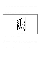
Upper Case Lead Wire Fig. 7 Removing Wires Connected to Control Panel 2. Construction and Location of the MX-85 Components At this time, the following main components of the MX-85 Printer and their respective locations can be observed: 1. Transformer & Filter Circuit Board 2. SMDP Board - Top 3. SMCT Board - Bottom 4. Printer Mechanism - M-3310 5. Control Panel -7-
-
 1
1 -
2
-
3
-
4
-
5
-
6
-
 7
7 -
 8
8 -
 9
9 -
 10
10 -
 11
11 -
 12
12 -
 13
13 -
 14
14 -
 15
15 -
 16
16 -
 17
17 -
18
-
19
-
20
-
21
-
22
-
23
-
24
-
25
-
26
-
27
-
28
-
29
-
30
-
31
-
32
-
33
-
34
-
35
-
36
 |
 |
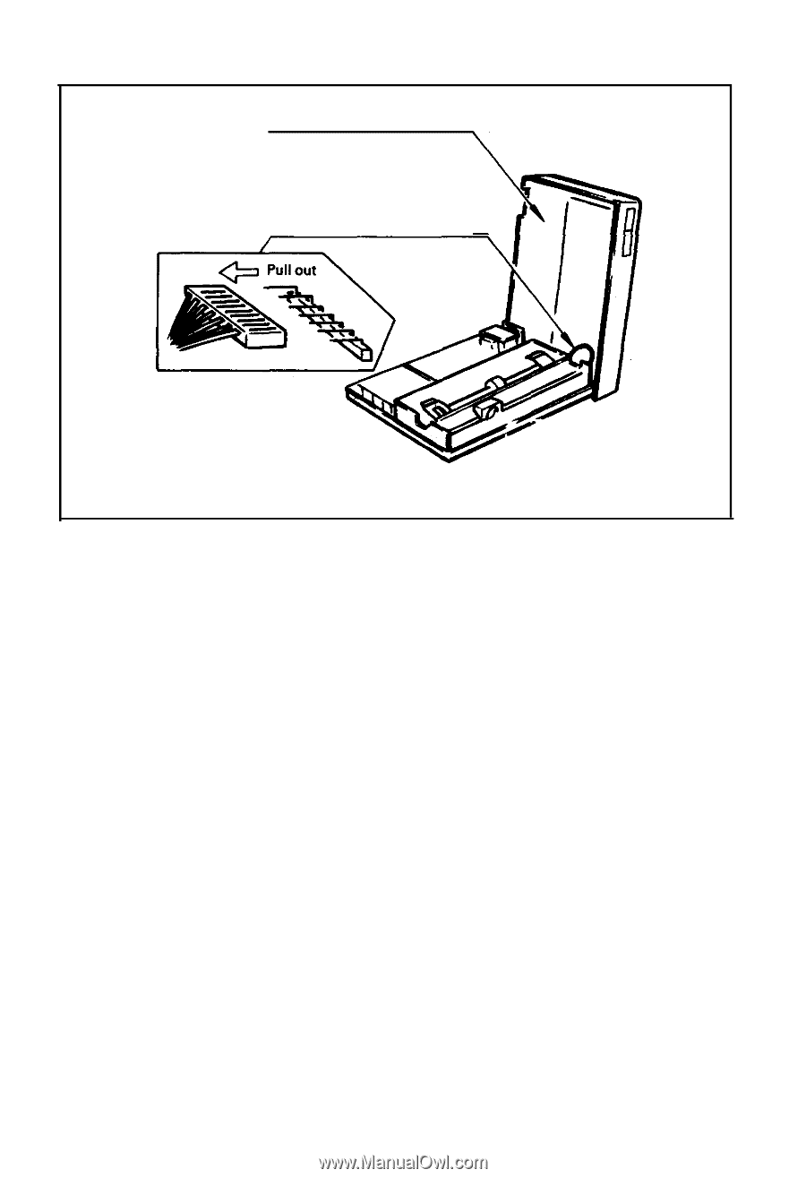
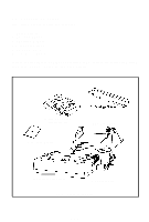
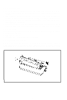
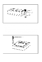
Upper Case
Lead Wire
Fig. 7
Removing Wires Connected to Control Panel
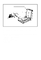
2. Construction and Location of the MX-85 Com-
ponents
At this time, the following main components of the MX-85 Printer and their
respective locations can be observed:
1. Transformer & Filter Circuit Board
2. SMDP Board - Top
3. SMCT Board - Bottom
4. Printer Mechanism - M-3310
5. Control Panel
-7-