Epson MX-85 User Manual - Page 14
Setting of DIP Switches and Jumpers, Setting DIP switches - SW-A and SW-B
 |
View all Epson MX-85 manuals
Add to My Manuals
Save this manual to your list of manuals |
Page 14 highlights
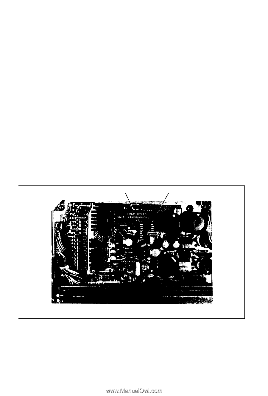
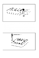
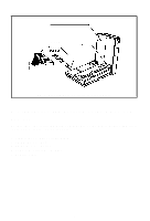
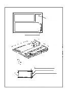
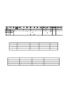
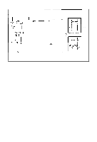
3. Setting of DIP Switches and Jumpers 3.1. Location of DIP switches and jumpers In order to suit each user's specific requirements, there are two (2) DIP (Dual In-Line Pin) switches located on the SMDP Board and sixteen (16) jumpers located on the SMCT Board. 3.2. Setting DIP switches - SW-A and SW-B 1. With the top cover removed, observe the SMDP Board and locate the two switches. They are equipped with plastic dust covers which pull off. Remove them and set aside for later replacement. The switches set to the left are "ON" and to the right are "OFF". 2. Tables 1 and 2 outline the function of each switch position. Be sure power is off when changing the position of any switch. 1) Switch B, the four (4) position switch, is used only to select correct baud rate. 2) Switch A, the eight (8) position switch, is used for code selection, word size, parity control and line feed control. The tables also note the factory-set conditions of both switches. DIP Switch A DIP Switch B Fig. 9 Location of DIP Switches -9-
-
 1
1 -
2
-
3
-
4
-
5
-
6
-
7
-
8
-
 9
9 -
 10
10 -
 11
11 -
 12
12 -
 13
13 -
 14
14 -
 15
15 -
 16
16 -
 17
17 -
 18
18 -
 19
19 -
20
-
21
-
22
-
23
-
24
-
25
-
26
-
27
-
28
-
29
-
30
-
31
-
32
-
33
-
34
-
35
-
36
 |
 |