Epson MX-85 User Manual - Page 4

Examples of Correct and Incorrect Ribbon Setting.., Switches and Indicators on Control Panel - matrix

Page 4 highlights

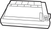
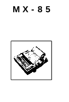
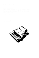
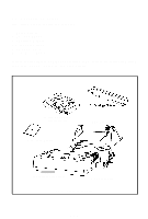
LIST OF FIGURES Fig. 1 MX-85 Dot Matrix Printer 1 Fig. 2 Contents of Carton 3 Fig. 3 Removal of Printer Cover 4 Fig. 4 Removal of Shipping Screws 5 Fig. 5 Removing Manual Paper Feed Knob 6 Fig. 6 Loosening All 4 Screws 6 Fig. 7 Removing Wires Connected to Control Panel 7 Fig. 8 Construction of the Printer 8 Fig. 9 Location of DIP Switches 9 Fig. 10 Setting DIP Switches 10 Fig. 11 Jumpers on the SMCT Board 13 Fig. 12 Setting of Power Supply Voltage 14 Fig. 13 Cartridge Ribbon Setting 15 Fig. 14 Cartridge Ribbon Setting 16 Fig. 15 Examples of Correct and Incorrect Ribbon Setting 16 Fig. 16 Loading of Roll Paper (1 17 Fig. 17 Loading of Roll Paper (2 18 Fig. 18 Loading of Roll Paper (3 18 Fig. 19 Cap Adjustment 19 Fig. 20 Switches and Indicators on Control Panel 20 Fig. 21 Cutting Paper 24 Fig. 22 Replacement of Print Head 26 -Ill-

  • 1
  • 2
  • 3
  • 4
  • 5
  • 6
  • 7
  • 8
  • 9
  • 10
  • 11
  • 12
  • 13
  • 14
  • 15
  • 16
  • 17
  • 18
  • 19
  • 20
  • 21
  • 22
  • 23
  • 24
  • 25
  • 26
  • 27
  • 28
  • 29
  • 30
  • 31
  • 32
  • 33
  • 34
  • 35
  • 36

LIST OF FIGURES
Fig.
1
MX-85 Dot Matrix Printer
...........................................................................
1
Fig.
2
Contents of Carton..
....................................................................................
3
Fig.
3
Removal of Printer Cover
...........................................................................
4
Fig.
4
Removal of Shipping Screws.
....................................................................
5
Fig.
5
Removing Manual Paper Feed Knob
........................................................
6
Fig.
6
Loosening All 4 Screws
..............................................................................
6
Fig.
7
Removing Wires Connected to Control Panel
.. ........................................
7
Fig.
8
Construction of the Printer..
.......................................................................
8
Fig.
9
Location of DIP Switches..
..........................................................................
9
Fig. 10
Setting DIP Switches
................................................................................
10
Fig. 11
Jumpers on the SMCT Board
..................................................................
13
Fig.
12
Setting of Power Supply Voltage..
..........................................................
14
Fig. 13 Cartridge Ribbon Setting
.........................................................................
15
Fig. 14 Cartridge Ribbon Setting
.........................................................................
16
Fig. 15
Examples of Correct and Incorrect Ribbon Setting..
.............................
16
Fig.
16
Loading of Roll Paper (1).
.........................................................................
17
Fig. 17
Loading of Roll Paper (2).
.........................................................................
18
Fig. 18
Loading of Roll Paper (3)
..........................................................................
18
Fig. 19
Cap Adjustment
........................................................................................
19
Fig.
20
Switches and Indicators on Control Panel
.............................................
20
Fig.
21
Cutting Paper
............................................................................................
24
Fig. 22
Replacement of Print Head
......................................................................
26
-Ill-