Epson MX-85 User Manual - Page 17
Setting of jumpers, Note 2
 |
View all Epson MX-85 manuals
Add to My Manuals
Save this manual to your list of manuals |
Page 17 highlights
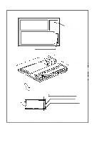
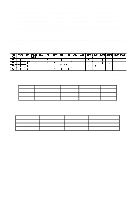
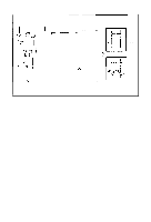
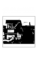
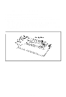
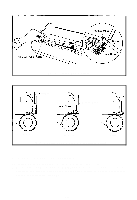
3.3. Setting of jumpers Your application may require the removal or installation of jumpers of the SMCT Board. Before continuing, consult Table 6 which outlines the function and factory-set condition of each jumper. In order to access the SMCT Board it is necessary to remove the SMDP Board. This is accomplished by: 1. Disconnecting the Mechanism Cable and the AC cable. 2. Removing the six (6) screws on the SMDP Board and the two (2) screws located in the heat sink on the right side of the board. 3. Lifting the Board from the rear center, in the connector area, to avoid damage. NOTE: Any changes in this area should be performed by an experienced technician. Jumper J1 J2 J3 J4 J5 J6 J7 J8 J9 J10 J11 J12 J13 J14 J15 J16 Table 6 Function and Conditions of Jumpers Not used ON RS-232C OFF Level Function OFF Current Loop ON Level Note 1 Both ON = Polar Both OFF = Neutral Not used Not used Current Loop (USA Version) Both are ON when not using RTS and CTS ON when using CTS ON when using RTS 80 mA Current Loop 60 mA Current Loop 40 mA Current Loop Note 2 20 mA Current Loop Factory-set OFF ON OFF OFF OFF OFF OFF ON ON ON OFF OFF OFF OFF OFF OFF Note 1: Select either J2 or J3. Do not connect both. Note 2: Select 1 only. Do not connect 2 or more. - 12-
-
 1
1 -
2
-
3
-
4
-
5
-
6
-
7
-
8
-
9
-
10
-
11
-
 12
12 -
 13
13 -
 14
14 -
 15
15 -
 16
16 -
 17
17 -
 18
18 -
 19
19 -
 20
20 -
 21
21 -
 22
22 -
23
-
24
-
25
-
26
-
27
-
28
-
29
-
30
-
31
-
32
-
33
-
34
-
35
-
36
 |
 |