Epson TM H6000 Technical Reference - Page 66
Connecting the Printer to the Host PC / POS Terminal
 |
View all Epson TM H6000 manuals
Add to My Manuals
Save this manual to your list of manuals |
Page 66 highlights
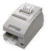
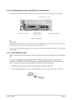
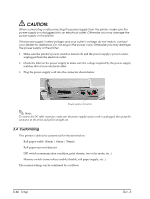
3.3.4 Connecting the Printer to the Host PC / POS Terminal All cables are connected to the connector panel located on the lower rear side of the printer. Drawer kick connector Interface connector Customer Display (DM-D) connector Power supply connector Connector panel Note: The figure above shows the connector panel for the RS-232/RS-485 interface model printer. The shape of the interface connector varies according to the type of interface used. Be sure to turn off the power supply for both the printer and the host computer unit before connecting the various cables. 3.3.4.1 Serial interface model Before connecting any of the cables, make sure that both the printer and the host PC are turned off. You need an appropriate serial, parallel, USB, or Ethernet interface cable to connect your computer to the printer. For the serial model, it is important that you use a null modem cable, not any other serial cable, and for the parallel model use an IEEE 1284 cable. 1. Plug the cable connector securely into the printer's interface connector. 2. If the cable connector has screws on it, tighten the screws on both sides of the connector. 3-12 Setup Rev. A
-
 1
1 -
2
-
3
-
4
-
5
-
6
-
7
-
8
-
9
-
10
-
11
-
12
-
13
-
14
-
15
-
16
-
17
-
18
-
19
-
20
-
21
-
22
-
23
-
24
-
25
-
26
-
27
-
28
-
29
-
30
-
31
-
32
-
33
-
34
-
35
-
36
-
37
-
38
-
39
-
40
-
41
-
42
-
43
-
44
-
45
-
46
-
47
-
48
-
49
-
50
-
51
-
52
-
53
-
54
-
55
-
56
-
57
-
58
-
59
-
60
-
 61
61 -
 62
62 -
 63
63 -
 64
64 -
 65
65 -
 66
66 -
 67
67 -
 68
68 -
 69
69 -
 70
70 -
 71
71 -
72
-
73
-
74
-
75
-
76
-
77
-
78
-
79
-
80
-
81
-
82
-
83
-
84
-
85
-
86
-
87
-
88
-
89
-
90
-
91
-
92
-
93
-
94
-
95
-
96
-
97
-
98
-
99
-
100
-
101
-
102
-
103
-
104
-
105
-
106
-
107
-
108
-
109
-
110
-
111
-
112
-
113
-
114
-
115
-
116
-
117
-
118
-
119
-
120
-
121
-
122
 |
 |
