Fujitsu MAB3091SC Product Manual - Page 136
Index, Connector signal Allocation
 |
View all Fujitsu MAB3091SC manuals
Add to My Manuals
Save this manual to your list of manuals |
Page 136 highlights
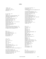
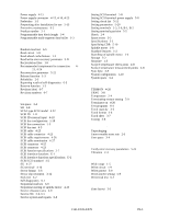
Index - SYNC 4-19 - Spindle Sync 4-19 16-bit SCSI 1-2, 4-15, 5-7 8-bit SCSI 1-2 A AC noise filter 4-14 Actuator 1-9 Additional error recovery parameters 5-21 Addressing of peripheral device 1-11 Air circulation 1-9 Air pressure adjustment hole 4-10 Allowable input current 4-12 Allowable input voltage 4-12 Alternate area 3-11 Alternate block allocation 3-12, 3-13, 3-14 Alternate cylinder 3-5 Alternate sector treatment 3-13 Alternate spare area 3-5 Atitute 2-4 Automatic alternate block allocation 3-16 Automatic alternate block reassignment 1-4 Average DE surface temperature 2-6 B BCRC 3-9 Basic operation test 6-5 Block address of user space 3-11 Block descriptor 5-18 Block descriptor 5-18 Breather filter 1-9 C C list 3-12 CE space 3-5 CN1 4-16, C-2, C-3 CN6 B-2 CN7 4-17, B-3 CSS 1-8 Cable connection 4-21 Cable connection requirements 4-24 Cable length 4-26 Caching parameters 5-23 Changing revision number at factory shipment 6- 7 Check before mounting 5-11 Check items at illegal operation 5-14 Checking SCSI connection 5-15, 5-16, 5-17 Checking at abnormal end 5-18 Checking procedure 5-15 Command queuing feature 1-3 Compactness 1-2 Confirming Operations after Installation for use 5-13 Confirming initial operations 5-13 Connection of terminating resistor 5-9 Connection requirements 4-14 Connections 5-3 Connector signal Allocation C-2 Connector signal allocation C-1 Connectors of terminals location 4-14, 4-22 Contact start/stop 1-8 Continuous block processing 1-3 Control mode parameters 5-23 Controller circuit 1-9 Current waveform 4-11 Cylinder configuration 3-1, 3-2 Cylinder skew 3-7 D D list 3-12 DC ground 4-27 DE 1-9 DISCON 4-20 Data field 3-8 Data format 3-1 Data security at power-failure 2-6 Data space 3-1 Default 5-10 Defect Management 3-12 Defect list 3-12 Defective block slipping 1-4 Delivery 5-2 Diagnosis 1-4 Diagnostics 6-1 Diagnostics and maintenance 6-1 Disable terminator connection 4-20 Disconnecting drives 5-24 Disconnection 5-22 Disk configuration 1-8 Disk enclosure 1-9 Disks 1-5 Drive parameter 5-19 Drive parameter 5-19 E ECC 3-9 Environmental requirements 2-4 Environmental specifications 2-4 Environmental temperature 4-8 C141-E035-03EN IN-1
-
 1
1 -
2
-
3
-
4
-
5
-
6
-
7
-
8
-
9
-
10
-
11
-
12
-
13
-
14
-
15
-
16
-
17
-
18
-
19
-
20
-
21
-
22
-
23
-
24
-
25
-
26
-
27
-
28
-
29
-
30
-
31
-
32
-
33
-
34
-
35
-
36
-
37
-
38
-
39
-
40
-
41
-
42
-
43
-
44
-
45
-
46
-
47
-
48
-
49
-
50
-
51
-
52
-
53
-
54
-
55
-
56
-
57
-
58
-
59
-
60
-
61
-
62
-
63
-
64
-
65
-
66
-
67
-
68
-
69
-
70
-
71
-
72
-
73
-
74
-
75
-
76
-
77
-
78
-
79
-
80
-
81
-
82
-
83
-
84
-
85
-
86
-
87
-
88
-
89
-
90
-
91
-
92
-
93
-
94
-
95
-
96
-
97
-
98
-
99
-
100
-
101
-
102
-
103
-
104
-
105
-
106
-
107
-
108
-
109
-
110
-
111
-
112
-
113
-
114
-
115
-
116
-
117
-
118
-
119
-
120
-
121
-
122
-
123
-
124
-
125
-
126
-
127
-
128
-
129
-
130
-
 131
131 -
 132
132 -
 133
133 -
 134
134 -
 135
135 -
 136
136 -
 137
137 -
 138
138 -
 139
139 -
 140
140 -
 141
141 -
142
 |
 |
