Fujitsu MAB3091SC Product Manual - Page 138
-6, B-1, B-2, Setting SCSI terminal
 |
View all Fujitsu MAB3091SC manuals
Add to My Manuals
Save this manual to your list of manuals |
Page 138 highlights
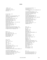
Power supply 4-15 Power supply connector 4-15, 4-16, 4-23 Prefetches 1-3 Preparating after Installation for use 5-13 Preventive maintenance 6-5 Product number 2-1 Programmable data block length 1-4 Programmable multi-segment data buffer 1-3 R Random read test 6-5 Read circuit 1-9 Read-ahead cache feature 1-3 Read/write error recovery parameter 5-21 Recirculation filter 1-9 Recommended components for connection 4- 21, 4-24 Reconnection parameter 5-22 Release function 1-3 Reliability 2-5 Reporting result of self-diagnostics 6-3 Reserve function 1-3 Revision label 6-7 Revision numbers 6-7 S SA space 3-4 SB 3-8 SCA2 type SCSI model 4-22 SCSI ID 1-11 SCSI ID external input 4-18 SCSI bus configuration 1-10 SCSI bus connection 5-3 SCSI bus test 6-5 SCSI cable 4-25 SCSI cable connector 4-25 SCSI cable requirements 4-26 SCSI cable termination 4-27 SCSI connector 4-15 SCSI connector 4-23 SCSI function specifications 2-7 SCSI interface functions E-1 SCSI interface functions specifications E-2 SCSI/CCS standard 1-2 SG 4-27 SG terminal 4-16 Sector format 3-8 Sector slip treatment 3-12 Seek test 6-2 Self-diagnostics 6-1 Sequential read test 6-5 Sequential starting of spindle motor 4-13 Service clearance area 4-9 Service life 2-6, 6-5 Service system and repairs 6-6 Setting SCSI terminal 5-8 Setting SCSI terminal power supply 5-8 Setting check list 5-11 Setting parameters 5-20 Setting terminals 5-5, 5-6, B-1, B-2 Setting terminals position 5-5 Shock 2-4 Spare sector 3-5 Specifications 2-1 Specifying CDB 5-19 Spindle motor 1-8 Standard features 1-2 Start/Stop of spindle motor 1-4 Storage 5-2 Structure 1-5 Surface temperature check point 4-8 Surface temperature measurement points 4-8 Sync byte 3-8 System configuration 1-10 System space 3-4 T TERMON 4-20 TRNG 3-8 Temperature 2-4 Terminating resistor setting 5-9 Terminator on 4-20 Test programs 6-4 Track capacity 3-3 Track format 3-6 Track skew 3-7 Trainig 3-8 U Unpackaging Unrecoverable error rate 2-5 User space 3-4 V Verify error recovery parameters 5-21 Vibration 2-4 W Wide range 1-5 Write circuit 1-9 Write protect 5-9 Write protect setting 5-9 Write/read test 6-2 Z Zone layout 3-3 C141-E035-03EN IN-3
-
 1
1 -
2
-
3
-
4
-
5
-
6
-
7
-
8
-
9
-
10
-
11
-
12
-
13
-
14
-
15
-
16
-
17
-
18
-
19
-
20
-
21
-
22
-
23
-
24
-
25
-
26
-
27
-
28
-
29
-
30
-
31
-
32
-
33
-
34
-
35
-
36
-
37
-
38
-
39
-
40
-
41
-
42
-
43
-
44
-
45
-
46
-
47
-
48
-
49
-
50
-
51
-
52
-
53
-
54
-
55
-
56
-
57
-
58
-
59
-
60
-
61
-
62
-
63
-
64
-
65
-
66
-
67
-
68
-
69
-
70
-
71
-
72
-
73
-
74
-
75
-
76
-
77
-
78
-
79
-
80
-
81
-
82
-
83
-
84
-
85
-
86
-
87
-
88
-
89
-
90
-
91
-
92
-
93
-
94
-
95
-
96
-
97
-
98
-
99
-
100
-
101
-
102
-
103
-
104
-
105
-
106
-
107
-
108
-
109
-
110
-
111
-
112
-
113
-
114
-
115
-
116
-
117
-
118
-
119
-
120
-
121
-
122
-
123
-
124
-
125
-
126
-
127
-
128
-
129
-
130
-
131
-
132
-
 133
133 -
 134
134 -
 135
135 -
 136
136 -
 137
137 -
 138
138 -
 139
139 -
 140
140 -
 141
141 -
 142
142
 |
 |
