Fujitsu MAB3091SC Product Manual - Page 84
Setting Terminals, s 5.3 shows SP models
 |
View all Fujitsu MAB3091SC manuals
Add to My Manuals
Save this manual to your list of manuals |
Page 84 highlights
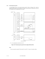
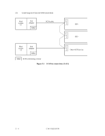
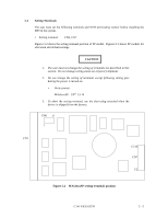
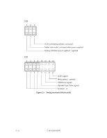
5.3 Setting Terminals The user must set the following terminals and SCSI terminating resistor before installing the IDD in the system. • Setting terminal: CN6, CN7 Figures 5.2 shows the setting terminal position of SP model. Figures 5.3 shows SP models for allocation and default settings. CAUTION 1. The user must not change the setting of terminals not described in this section. Do not change setting status set at factory shipment. 2. Do not change the setting of terminals except following setting pins during the power is turned on. • Write protect MAx3xxxSP: CN7 13-14 3. To short the setting terminal, use the short plug attached when the device is shipped from the factory. CN6 6 1 CN1 15/16 CN7 1/2 Figure 5.2 MAx3xxxSP setting terminals position C141-E035-02EN 5 - 5
-
 1
1 -
2
-
3
-
4
-
5
-
6
-
7
-
8
-
9
-
10
-
11
-
12
-
13
-
14
-
15
-
16
-
17
-
18
-
19
-
20
-
21
-
22
-
23
-
24
-
25
-
26
-
27
-
28
-
29
-
30
-
31
-
32
-
33
-
34
-
35
-
36
-
37
-
38
-
39
-
40
-
41
-
42
-
43
-
44
-
45
-
46
-
47
-
48
-
49
-
50
-
51
-
52
-
53
-
54
-
55
-
56
-
57
-
58
-
59
-
60
-
61
-
62
-
63
-
64
-
65
-
66
-
67
-
68
-
69
-
70
-
71
-
72
-
73
-
74
-
75
-
76
-
77
-
78
-
 79
79 -
 80
80 -
 81
81 -
 82
82 -
 83
83 -
 84
84 -
 85
85 -
 86
86 -
 87
87 -
 88
88 -
 89
89 -
90
-
91
-
92
-
93
-
94
-
95
-
96
-
97
-
98
-
99
-
100
-
101
-
102
-
103
-
104
-
105
-
106
-
107
-
108
-
109
-
110
-
111
-
112
-
113
-
114
-
115
-
116
-
117
-
118
-
119
-
120
-
121
-
122
-
123
-
124
-
125
-
126
-
127
-
128
-
129
-
130
-
131
-
132
-
133
-
134
-
135
-
136
-
137
-
138
-
139
-
140
-
141
-
142
 |
 |
