Fujitsu MAB3091SC Product Manual - Page 137
MODE SELECT EXTENDED command, MODE SELECT command
 |
View all Fujitsu MAB3091SC manuals
Add to My Manuals
Save this manual to your list of manuals |
Page 137 highlights
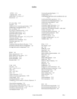
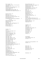
Error indication of self-diagnostics 6-3 Error rate 2-5 Error recovery 1-4 Error recovery during self-diagnostics 6-3 Error recovery parameters 5-21 External dimensions 4-1, 4-2, 4-3, 4-4, 4-5 External inputs for operating terminating resistor 4-20 External magnetic field 4-9 External operator panel 4-27, 4-28 External operator panel circuit example 4-28 External operator panel connector 4-16, 4-17 External operator panel connector signals 4-18 F FG 4-27 FORMAT UNIT command 5-19 Format capacity 3-10 Format parameter 5-19 Formatting 2-6 Function specifications 2-2 G G list 3-12 G1 3-8 Gaps 3-8 General description 1-1 General notes 5-1 General notes 5-1 H Hardware function test 6-2 Head configuration 1-8 Heads 1-8 High speed data transfer 1-2 High speed positioning 1-4 Humidity 2-4 I Indicating revision number 6-7 Initial self-diagnostics 6-2 Input signal 4-19, 4-20 Installation 5-1, 5-2 Installation requirements 4-1 Inteface connector 4-15 Interface test 6-5 Internal test space 3-4 L LBA 3-8 LUN 1-11 Large capacity 1-4 Leak magnetic flux 4-9 Limitation of side-mounting 4-6 Location of connector A-2 Logical data block addressing 3-11 Low noise 1-5 Low power consumption 1-5 Low vibration 1-5 M MODE SELECT EXTENDED command 5-18 MODE SELECT command 5-18 MPU 1-8 MR 1-8 MTBF 2-5 MTTR 2-5 Magnet - Resistive 1-8 Maintenance information 6-5 Maintenance requirements 6-5 Microcode downloading 1-8 Microprocessing unit 1-9 Mode setting 5-8 Mode settings 5-10 Model name 2-1, D-1, D-2 Motor start mode 5-8 Motor start mode setting 5-8 Mounting drives 5-11 Mounting frame structure 4-6 Mounting orientation 4-6 Mounting procedure 5-11 Mounting requirements 4-1 N Noise filter 4-13 Notes on mounting 4-6 O Online self-diagnostics 6-3 Outer view 1-5, 1-6, 1-7 Output signal 4-19 Output signal for external LED 4-19 P PAD 1 3-9 PAD 2 3-9 PAD 3 3-9 PLO sync 3-8 PR4ML 1-8 Packaging 5-2 Partial response class 4 maximum likelihood 1-9 Parts that can be replaced in the field 6-6 Physical sector allocation 3-6 Positioning error rate 2-5 Power cable 4-27 Power on/off sequence 4-11, 4-12 Power requirements 2-4, 4-11 IN-2 C141-E035-03EN
-
 1
1 -
2
-
3
-
4
-
5
-
6
-
7
-
8
-
9
-
10
-
11
-
12
-
13
-
14
-
15
-
16
-
17
-
18
-
19
-
20
-
21
-
22
-
23
-
24
-
25
-
26
-
27
-
28
-
29
-
30
-
31
-
32
-
33
-
34
-
35
-
36
-
37
-
38
-
39
-
40
-
41
-
42
-
43
-
44
-
45
-
46
-
47
-
48
-
49
-
50
-
51
-
52
-
53
-
54
-
55
-
56
-
57
-
58
-
59
-
60
-
61
-
62
-
63
-
64
-
65
-
66
-
67
-
68
-
69
-
70
-
71
-
72
-
73
-
74
-
75
-
76
-
77
-
78
-
79
-
80
-
81
-
82
-
83
-
84
-
85
-
86
-
87
-
88
-
89
-
90
-
91
-
92
-
93
-
94
-
95
-
96
-
97
-
98
-
99
-
100
-
101
-
102
-
103
-
104
-
105
-
106
-
107
-
108
-
109
-
110
-
111
-
112
-
113
-
114
-
115
-
116
-
117
-
118
-
119
-
120
-
121
-
122
-
123
-
124
-
125
-
126
-
127
-
128
-
129
-
130
-
131
-
 132
132 -
 133
133 -
 134
134 -
 135
135 -
 136
136 -
 137
137 -
 138
138 -
 139
139 -
 140
140 -
 141
141 -
 142
142
 |
 |