Fujitsu MAB3091SC Product Manual - Page 75
Cable connector requirements, Table 4.3, Recommended components for connection
 |
View all Fujitsu MAB3091SC manuals
Add to My Manuals
Save this manual to your list of manuals |
Page 75 highlights
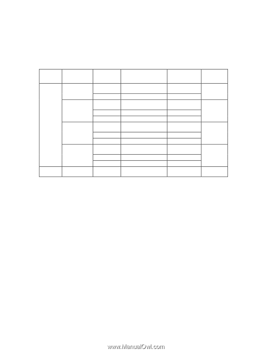
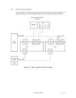
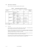
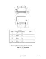
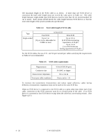
4.3.3 Cable connector requirements Table 4.3 lists the recommended components cable connection. Table 4.3 Recommended components for connection Applicable model Name Par number MAx3xxxSP SCSI cable (CN1) Cable socket 786090-7 (closed-end type) Signal cable - Power supply cable Cable socket (CN1) housing 1-480424-0 Contact 60619-4 Cable 60617-4 External operator Cable socket panel (CN1) housing FCN-723J012/2M Contact FCN-723J-G/AM Cable AWG26 to 34 External operator Cable socket panel (CN7) housing FCN-723J016/2M Contact FCN-723J-G/AM Cable AWG28 MAx3xxxSC SCSI connector (CN1) Connector 787311-1 Manufacturer AMP - AMP Fujitsu Limited Fujitsu Limited Fujitsu Limited Fujitsu Limited AMP Reference (Figures 4.23 and 4.28) S1 S2 S3 S4 (1) SCSI cable All SCSI devices on one bus are daisy-chained with an SCSI cable. A terminating resistor must be mounted in the SCSI device at each end of the SCSI cable. Because an SCSI terminating resistor module has been mounted in the IDD of single-ended type SCSI at factory shipment, it must be set to not-connection when the IDD is not connected at either end of the SCSI cable. See Section 5.3 for details. The maximum number of SCSI devices that can be connected to the SCSI bus is 16 for the 16bit SCSI, including the host adapter, IDD, and other SCSI equipment. For the 16-bit SCSI, the connector for the SCSI cable must be an unshielded 68-contact socket having 34-contact rows spaced 1.27 mm (0.05 inch) apart. (See Figure 4.26.) 4 - 24 C141-E035-02EN
-
 1
1 -
2
-
3
-
4
-
5
-
6
-
7
-
8
-
9
-
10
-
11
-
12
-
13
-
14
-
15
-
16
-
17
-
18
-
19
-
20
-
21
-
22
-
23
-
24
-
25
-
26
-
27
-
28
-
29
-
30
-
31
-
32
-
33
-
34
-
35
-
36
-
37
-
38
-
39
-
40
-
41
-
42
-
43
-
44
-
45
-
46
-
47
-
48
-
49
-
50
-
51
-
52
-
53
-
54
-
55
-
56
-
57
-
58
-
59
-
60
-
61
-
62
-
63
-
64
-
65
-
66
-
67
-
68
-
69
-
 70
70 -
 71
71 -
 72
72 -
 73
73 -
 74
74 -
 75
75 -
 76
76 -
 77
77 -
 78
78 -
 79
79 -
 80
80 -
81
-
82
-
83
-
84
-
85
-
86
-
87
-
88
-
89
-
90
-
91
-
92
-
93
-
94
-
95
-
96
-
97
-
98
-
99
-
100
-
101
-
102
-
103
-
104
-
105
-
106
-
107
-
108
-
109
-
110
-
111
-
112
-
113
-
114
-
115
-
116
-
117
-
118
-
119
-
120
-
121
-
122
-
123
-
124
-
125
-
126
-
127
-
128
-
129
-
130
-
131
-
132
-
133
-
134
-
135
-
136
-
137
-
138
-
139
-
140
-
141
-
142
 |
 |