Fujitsu MAB3091SC Product Manual - Page 42
Track skew/cylinder skew
 |
View all Fujitsu MAB3091SC manuals
Add to My Manuals
Save this manual to your list of manuals |
Page 42 highlights
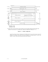
(2) Track skew and cylinder skew To avoid waiting for one turn involved in head and cylinder switching, the first logical data block in each track is shifted by the number of sectors (track skew and cylinder skew) corresponding to the switching time. Figure 3.5 shows how the data block is allocated in each track. At the head switching location in a cylinder, the first logical data block in track t + 1 is allocated at the sector position which locates the track skew behind the sector position of the last logical data block sector in track t. At the cylinder switching location, like the head switching location, the first logical data block in a cylinder is allocated at the sector position which locates the cylinder skew behind the last logical sector position in the preceding cylinder. The last logical sector in the cylinder is allocated when formatting, and is an unused spare sector. Figure 3.5 Track skew/cylinder skew The number of physical sectors (track skew factor and cylinder skew factor) corresponding to the skew time varies depending on the logical data block length because the track skew and the cylinder skew are managed for individual sectors. The IDD automatically determines appropriate values for the track skew factor and the cylinder skew factor according to the specified logical data block length. The value can be read out by the MODE SENSE or MODE SENSE EXTENDED command after the track has been formatted. C141-E035-02EN 3 - 7
-
 1
1 -
2
-
3
-
4
-
5
-
6
-
7
-
8
-
9
-
10
-
11
-
12
-
13
-
14
-
15
-
16
-
17
-
18
-
19
-
20
-
21
-
22
-
23
-
24
-
25
-
26
-
27
-
28
-
29
-
30
-
31
-
32
-
33
-
34
-
35
-
36
-
 37
37 -
 38
38 -
 39
39 -
 40
40 -
 41
41 -
 42
42 -
 43
43 -
 44
44 -
 45
45 -
 46
46 -
 47
47 -
48
-
49
-
50
-
51
-
52
-
53
-
54
-
55
-
56
-
57
-
58
-
59
-
60
-
61
-
62
-
63
-
64
-
65
-
66
-
67
-
68
-
69
-
70
-
71
-
72
-
73
-
74
-
75
-
76
-
77
-
78
-
79
-
80
-
81
-
82
-
83
-
84
-
85
-
86
-
87
-
88
-
89
-
90
-
91
-
92
-
93
-
94
-
95
-
96
-
97
-
98
-
99
-
100
-
101
-
102
-
103
-
104
-
105
-
106
-
107
-
108
-
109
-
110
-
111
-
112
-
113
-
114
-
115
-
116
-
117
-
118
-
119
-
120
-
121
-
122
-
123
-
124
-
125
-
126
-
127
-
128
-
129
-
130
-
131
-
132
-
133
-
134
-
135
-
136
-
137
-
138
-
139
-
140
-
141
-
142
 |
 |
