Fujitsu MAB3091SC Product Manual - Page 92
Confirming Operations after Installation and Preparation for use
 |
View all Fujitsu MAB3091SC manuals
Add to My Manuals
Save this manual to your list of manuals |
Page 92 highlights
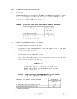
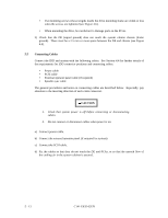
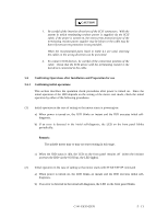
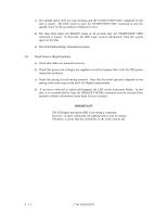
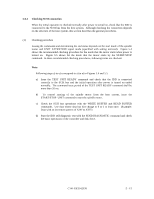
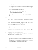
CAUTION 1. Be careful of the insertion directions of the SCSI connectors. With the system in which terminating resistor power is supplied via the SCSI cable, if the power is turned on, the overcurrent protection fuse of the terminating resistor power supplier may be blown or the cable may be burnt if overcurrent protection is not provided. When the recommended parts listed in Table 4.1 are used, inserting the cables in the wrong direction can be prevented. 2. To connect SCSI devices, be careful of the connection position of the cable. Check that the SCSI device with the terminating resistor is the last device connected to the cable. 5.6 Confirming Operations after Installation and Preparation for use 5.6.1 Confirming initial operations This section describes the operation check procedures after power is turned on. Since the initial operation of the IDD depends on the setting of the motor start mode, check the initial operation by either of the following procedures. (1) Initial operation in the case of setting so that motor starts at powering-on a) When power is turned on, the LED blinks an instant and the IDD executes initial selfdiagnosis. b) If an error is detected in the initial self-diagnosis, the LED on the front panel blinks periodically. Remark: The spindle motor may or may not start rotating in this stage. c) When the IDD status is idle, the LED on the front panel remains off (when the initiator accesses the IDD via the SCSI bus, the LED lights). (2) Initial operation in the case of setting so that motor starts with START/STOP command a) When power is turned on, the LED blinks an instant and the IDD executes initial selfdiagnosis. b) If an error is detected in the initial self-diagnosis, the LED on the front panel blinks. C141-E035-02EN 5 - 13
-
 1
1 -
2
-
3
-
4
-
5
-
6
-
7
-
8
-
9
-
10
-
11
-
12
-
13
-
14
-
15
-
16
-
17
-
18
-
19
-
20
-
21
-
22
-
23
-
24
-
25
-
26
-
27
-
28
-
29
-
30
-
31
-
32
-
33
-
34
-
35
-
36
-
37
-
38
-
39
-
40
-
41
-
42
-
43
-
44
-
45
-
46
-
47
-
48
-
49
-
50
-
51
-
52
-
53
-
54
-
55
-
56
-
57
-
58
-
59
-
60
-
61
-
62
-
63
-
64
-
65
-
66
-
67
-
68
-
69
-
70
-
71
-
72
-
73
-
74
-
75
-
76
-
77
-
78
-
79
-
80
-
81
-
82
-
83
-
84
-
85
-
86
-
 87
87 -
 88
88 -
 89
89 -
 90
90 -
 91
91 -
 92
92 -
 93
93 -
 94
94 -
 95
95 -
 96
96 -
 97
97 -
98
-
99
-
100
-
101
-
102
-
103
-
104
-
105
-
106
-
107
-
108
-
109
-
110
-
111
-
112
-
113
-
114
-
115
-
116
-
117
-
118
-
119
-
120
-
121
-
122
-
123
-
124
-
125
-
126
-
127
-
128
-
129
-
130
-
131
-
132
-
133
-
134
-
135
-
136
-
137
-
138
-
139
-
140
-
141
-
142
 |
 |
