HP 11-f100 Maintenance and Service Guide - Page 38
Remove the Phillips PM2.0×3.3 screw, be installed on the antenna connector
 |
View all HP 11-f100 manuals
Add to My Manuals
Save this manual to your list of manuals |
Page 38 highlights
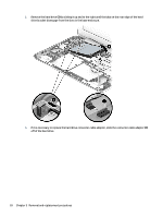
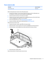
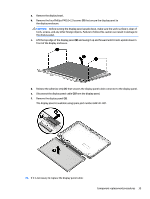
NOTE: The #1/white WLAN antenna cable connects to the WLAN module #1/Main terminal. The #2/ black WLAN antenna cable connects to the WLAN module #1/Aux terminal. 2. Remove the Phillips PM2.0×3.3 screw (2) that secures the WLAN module to the base enclosure. (The WLAN module tilts up.) 3. Remove the WLAN module (3) by pulling the module away from the slot at an angle. NOTE: If the WLAN antenna is not connected to the terminal on the WLAN module, a protective sleeve must be installed on the antenna connector, as shown in the following illustration. Reverse this procedure to install the WLAN module. 30 Chapter 5 Removal and replacement procedures
-
 1
1 -
2
-
3
-
4
-
5
-
6
-
7
-
8
-
9
-
10
-
11
-
12
-
13
-
14
-
15
-
16
-
17
-
18
-
19
-
20
-
21
-
22
-
23
-
24
-
25
-
26
-
27
-
28
-
29
-
30
-
31
-
32
-
 33
33 -
 34
34 -
 35
35 -
 36
36 -
 37
37 -
 38
38 -
 39
39 -
 40
40 -
 41
41 -
 42
42 -
 43
43 -
44
-
45
-
46
-
47
-
48
-
49
-
50
-
51
-
52
-
53
-
54
-
55
-
56
-
57
-
58
-
59
-
60
-
61
-
62
-
63
-
64
-
65
-
66
-
67
-
68
-
69
-
70
-
71
-
72
-
73
-
74
-
75
-
76
-
77
 |
 |

NOTE:
The #1/white WLAN antenna cable connects to the WLAN module #1/Main terminal. The #2/
black WLAN antenna cable connects to the WLAN module #1/Aux terminal.
2.
Remove the Phillips PM2.0×3.3 screw
(2)
that secures the WLAN module to the base enclosure. (The
WLAN module tilts up.)
3.
Remove the WLAN module
(3)
by pulling the module away from the slot at an angle.
NOTE:
If the WLAN antenna is not connected to the terminal on the WLAN module, a protective sleeve must
be installed on the antenna connector, as shown in the following illustration.
Reverse this procedure to install the WLAN module.
30
Chapter 5
Removal and replacement procedures