HP 11-f100 Maintenance and Service Guide - Page 44
Release the display panel cable from the retention clips, built into the left edge of the display
 |
View all HP 11-f100 manuals
Add to My Manuals
Save this manual to your list of manuals |
Page 44 highlights
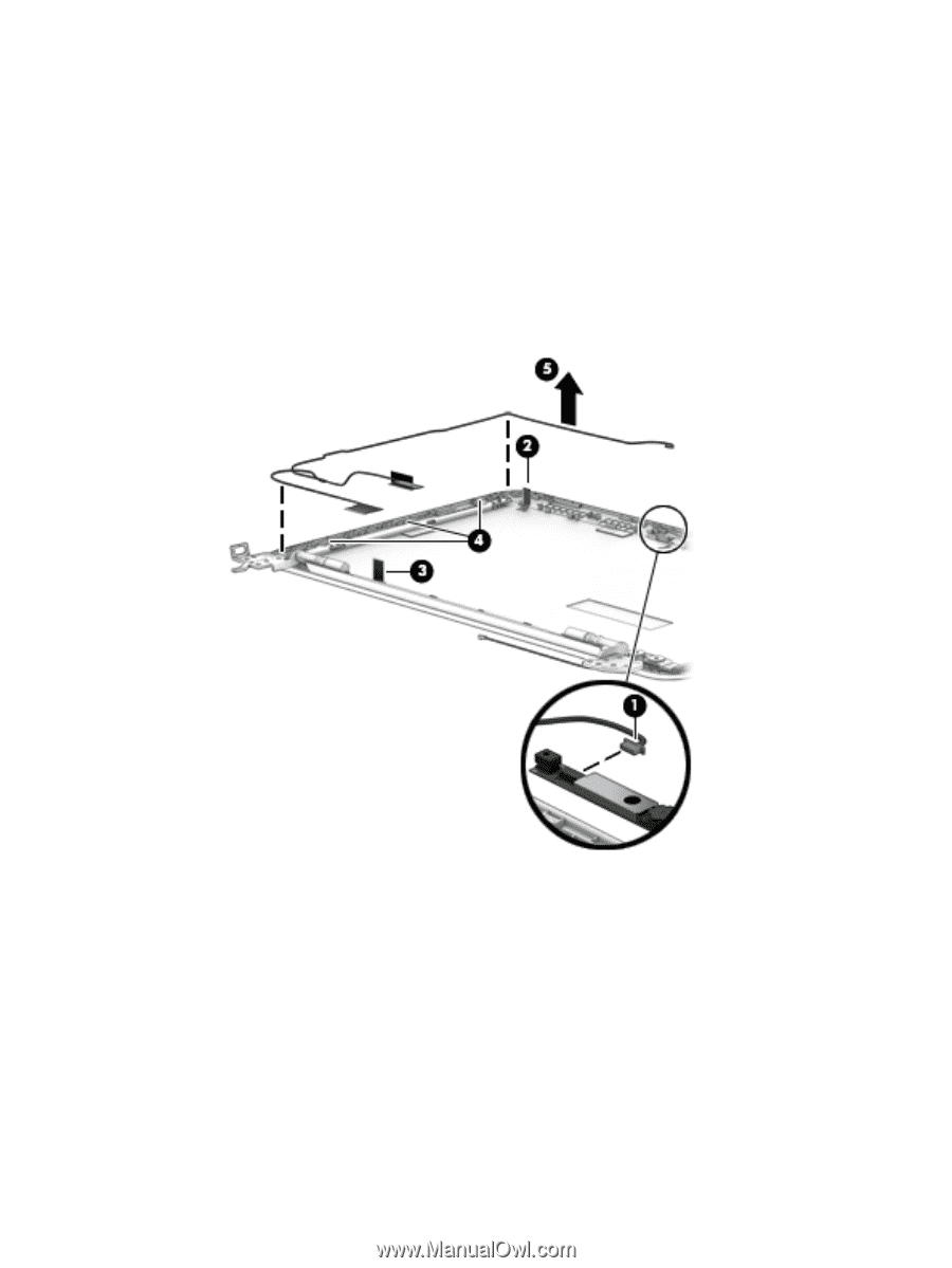
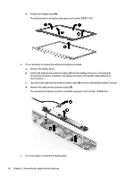
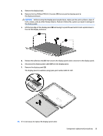
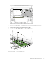
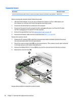
a. Remove the display bezel. b. Remove the display panel. c. Disconnect the display panel cable (1) from the webcam/microphone module. d. Release the grounding tape (2) and (3) that secures the display panel cable to the display enclosure. e. Release the display panel cable from the retention clips (4) built into the left edge of the display enclosure. f. Remove the display panel cable (5). The display panel cable is available using spare part number 809937-001. 11. If it is necessary to replace the display hinges: a. Remove the display bezel. b. Remove the display panel. c. Remove the two Phillips PM2.0×3.3 screws (1) and the four Phillips PM2.5×3.7 broad head screws (2) that secure the display hinges to the display enclosure. 36 Chapter 5 Removal and replacement procedures
-
 1
1 -
2
-
3
-
4
-
5
-
6
-
7
-
8
-
9
-
10
-
11
-
12
-
13
-
14
-
15
-
16
-
17
-
18
-
19
-
20
-
21
-
22
-
23
-
24
-
25
-
26
-
27
-
28
-
29
-
30
-
31
-
32
-
33
-
34
-
35
-
36
-
37
-
38
-
 39
39 -
 40
40 -
 41
41 -
 42
42 -
 43
43 -
 44
44 -
 45
45 -
 46
46 -
 47
47 -
 48
48 -
 49
49 -
50
-
51
-
52
-
53
-
54
-
55
-
56
-
57
-
58
-
59
-
60
-
61
-
62
-
63
-
64
-
65
-
66
-
67
-
68
-
69
-
70
-
71
-
72
-
73
-
74
-
75
-
76
-
77
 |
 |