HP 11-f100 Maintenance and Service Guide - Page 48
Connector board, Remove the Philllips PM2.0×3.3 screw
 |
View all HP 11-f100 manuals
Add to My Manuals
Save this manual to your list of manuals |
Page 48 highlights
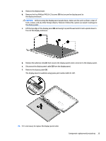
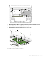
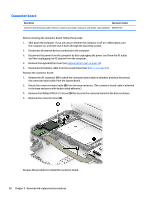
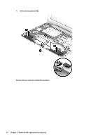
Connector board Description Spare part number Connector board (includes cable, USB port, memory card reader, audio jack, and double-sided adhesive) 809788-001 Before removing the connector board, follow these steps: 1. Shut down the computer. If you are unsure whether the computer is off or in Hibernation, turn the computer on, and then shut it down through the operating system. 2. Disconnect all external devices connected to the computer. 3. Disconnect the power from the computer by first unplugging the power cord from the AC outlet and then unplugging the AC adapter from the computer. 4. Remove the keyboard/top cover (see Keyboard/top cover on page 20). 5. Disconnect the battery cable from the system board (see Battery on page 26). Remove the connector board: 1. Release the ZIF connector (1) to which the connector board cable is attached, and then disconnect the connector board cable from the system board. 2. Detach the connector board cable (2) from the base enclosure. (The connector board cable is attached to the base enclosure with double-sided adhesive.) 3. Remove the Philllips PM2.0×3.3 screw (3) that secures the connector board to the base enclosure. 4. Remove the connector board (4). Reverse this procedure to install the connector board. 40 Chapter 5 Removal and replacement procedures
-
 1
1 -
2
-
3
-
4
-
5
-
6
-
7
-
8
-
9
-
10
-
11
-
12
-
13
-
14
-
15
-
16
-
17
-
18
-
19
-
20
-
21
-
22
-
23
-
24
-
25
-
26
-
27
-
28
-
29
-
30
-
31
-
32
-
33
-
34
-
35
-
36
-
37
-
38
-
39
-
40
-
41
-
42
-
 43
43 -
 44
44 -
 45
45 -
 46
46 -
 47
47 -
 48
48 -
 49
49 -
 50
50 -
 51
51 -
 52
52 -
 53
53 -
54
-
55
-
56
-
57
-
58
-
59
-
60
-
61
-
62
-
63
-
64
-
65
-
66
-
67
-
68
-
69
-
70
-
71
-
72
-
73
-
74
-
75
-
76
-
77
 |
 |
