HP 11-f100 Maintenance and Service Guide - Page 41
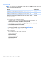
Flex the inside edges of the top edge, the display assembly.
 |
View all HP 11-f100 manuals
Add to My Manuals
Save this manual to your list of manuals |
Page 41 highlights
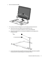
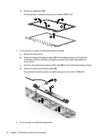
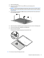
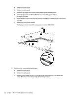
6. Remove the display assembly (2). 7. If it is necessary to replace the display bezel or any of the display assembly subcomponents: a. Remove the two screw covers (1) that conceal the display bezel screws. The screw covers are included in the Rubber Kit, spare part number 809790-001. b. Remove the two Phillips PM 2.0×2.2 broad head screws (2) that secure the display bezel to the display assembly. c. Flex the inside edges of the top edge (1), the left and right sides (2), and the bottom edge (3) of the display bezel until the bezel disengages from the display enclosure. Component replacement procedures 33
-
 1
1 -
2
-
3
-
4
-
5
-
6
-
7
-
8
-
9
-
10
-
11
-
12
-
13
-
14
-
15
-
16
-
17
-
18
-
19
-
20
-
21
-
22
-
23
-
24
-
25
-
26
-
27
-
28
-
29
-
30
-
31
-
32
-
33
-
34
-
35
-
 36
36 -
 37
37 -
 38
38 -
 39
39 -
 40
40 -
 41
41 -
 42
42 -
 43
43 -
 44
44 -
 45
45 -
 46
46 -
47
-
48
-
49
-
50
-
51
-
52
-
53
-
54
-
55
-
56
-
57
-
58
-
59
-
60
-
61
-
62
-
63
-
64
-
65
-
66
-
67
-
68
-
69
-
70
-
71
-
72
-
73
-
74
-
75
-
76
-
77
 |
 |

6.
Remove the display assembly
(2)
.
7.
If it is necessary to replace the display bezel or any of the display assembly subcomponents:
a.
Remove the two screw covers
(1)
that conceal the display bezel screws.
The screw covers are included in the Rubber Kit, spare part number 809790-001.
b.
Remove the two Phillips PM 2.0×2.2 broad head screws
(2)
that secure the display bezel to
the display assembly.
c.
Flex the inside edges of the top edge
(1)
, the left and right sides
(2)
, and the bottom edge
(3)
of
the display bezel until the bezel disengages from the display enclosure.
Component replacement procedures
33