HP 11-f100 Maintenance and Service Guide - Page 47
by sliding it up and to the left at an angle., Reverse this procedure to install the system board.
 |
View all HP 11-f100 manuals
Add to My Manuals
Save this manual to your list of manuals |
Page 47 highlights
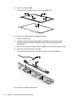
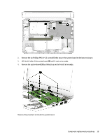
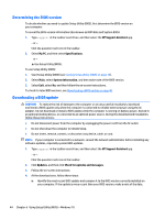
2. Remove the six Philllips PM2.0×2.3 screws (1) that secure the system board to the base enclosure. 3. Lift the left side of the system board (2) until it rests at an angle. 4. Remove the system board (3) by sliding it up and to the left at an angle. Reverse this procedure to install the system board. Component replacement procedures 39
-
 1
1 -
2
-
3
-
4
-
5
-
6
-
7
-
8
-
9
-
10
-
11
-
12
-
13
-
14
-
15
-
16
-
17
-
18
-
19
-
20
-
21
-
22
-
23
-
24
-
25
-
26
-
27
-
28
-
29
-
30
-
31
-
32
-
33
-
34
-
35
-
36
-
37
-
38
-
39
-
40
-
41
-
 42
42 -
 43
43 -
 44
44 -
 45
45 -
 46
46 -
 47
47 -
 48
48 -
 49
49 -
 50
50 -
 51
51 -
 52
52 -
53
-
54
-
55
-
56
-
57
-
58
-
59
-
60
-
61
-
62
-
63
-
64
-
65
-
66
-
67
-
68
-
69
-
70
-
71
-
72
-
73
-
74
-
75
-
76
-
77
 |
 |

2.
Remove the six Philllips PM2.0×2.3 screws
(1)
that secure the system board to the base enclosure.
3.
Lift the left side of the system board
(2)
until it rests at an angle.
4.
Remove the system board
(3)
by sliding it up and to the left at an angle.
Reverse this procedure to install the system board.
Component replacement procedures
39