HP 14-bp100 Maintenance and Service Guide - Page 53
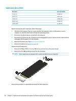
UMA graphics models with 15 W Intel Core processors, the four screws
 |
View all HP 14-bp100 manuals
Add to My Manuals
Save this manual to your list of manuals |
Page 53 highlights
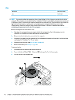
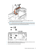
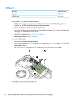
● Thermal paste is used on the processor (1) and associated heat sink area (2), as well as the graphics chip (3) and associated heat sink area (4). NOTE: The thermal material must be thoroughly cleaned from the surfaces of the heat sink and the system board components each time the heat sink is removed. Replacement thermal material is included with the heat sink, processor, and system board spare part kits. 3. UMA graphics models with 15 W Intel Core processors: In the order indicated on the heat sink, remove the four screws (1) that secure the heat sink to the system board. 4. Remove the heat sink from the system board (2). Component replacement procedures 45
-
 1
1 -
2
-
3
-
4
-
5
-
6
-
7
-
8
-
9
-
10
-
11
-
12
-
13
-
14
-
15
-
16
-
17
-
18
-
19
-
20
-
21
-
22
-
23
-
24
-
25
-
26
-
27
-
28
-
29
-
30
-
31
-
32
-
33
-
34
-
35
-
36
-
37
-
38
-
39
-
40
-
41
-
42
-
43
-
44
-
45
-
46
-
47
-
 48
48 -
 49
49 -
 50
50 -
 51
51 -
 52
52 -
 53
53 -
 54
54 -
 55
55 -
 56
56 -
 57
57 -
 58
58 -
59
-
60
-
61
-
62
-
63
-
64
-
65
-
66
-
67
-
68
-
69
-
70
-
71
-
72
-
73
-
74
-
75
-
76
-
77
-
78
-
79
-
80
-
81
-
82
-
83
-
84
-
85
-
86
-
87
-
88
-
89
-
90
-
91
-
92
-
93
-
94
-
95
-
96
-
97
-
98
 |
 |
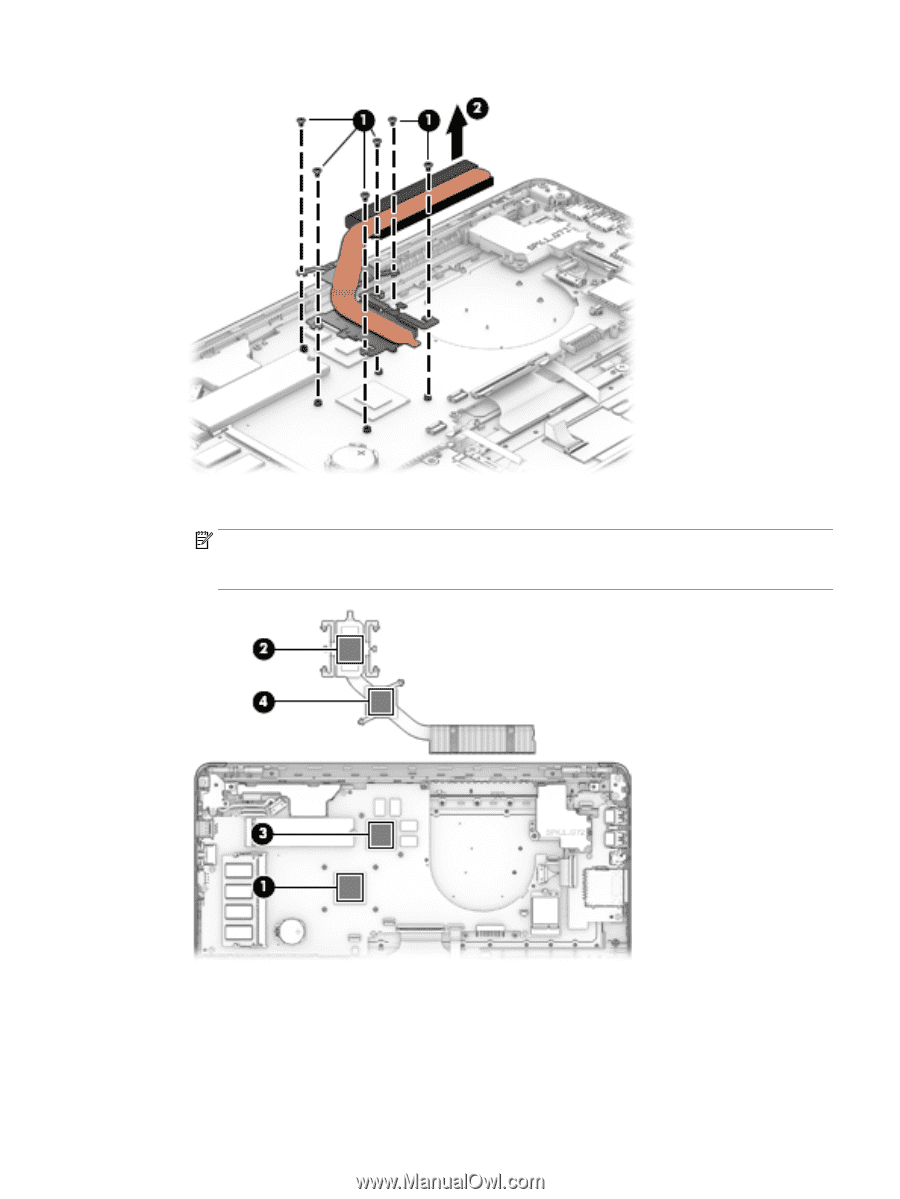
●
Thermal paste is used on the processor
(1)
and associated heat sink area
(2)
, as well as the
graphics chip
(3)
and associated heat sink area
(4)
.
NOTE:
The thermal material must be thoroughly cleaned from the surfaces of the heat sink and
the system board components each time the heat sink is removed. Replacement thermal material
is included with the heat sink, processor, and system board spare part kits.
3.
UMA graphics models with 15 W Intel Core processors:
In the order indicated on the heat sink, remove
the four screws
(1)
that secure the heat sink to the system board.
4.
Remove the heat sink from the system board
(2)
.
Component replacement procedures
45