HP 14-bp100 Maintenance and Service Guide - Page 70
Reverse this procedure to reassemble and install the display assembly.
 |
View all HP 14-bp100 manuals
Add to My Manuals
Save this manual to your list of manuals |
Page 70 highlights
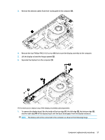
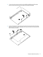
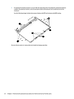
7. If replacing the display enclosure, be sure that the subcomponents (including the camera/microphone module, the antenna receivers, and all associated cables and hardware) are transferred to the new enclosure. Use the following image to determine proper display cable (1) and antenna cable (2) routing. Reverse this procedure to reassemble and install the display assembly. 62 Chapter 5 Removal and replacement procedures for Authorized Service Provider parts
-
 1
1 -
2
-
3
-
4
-
5
-
6
-
7
-
8
-
9
-
10
-
11
-
12
-
13
-
14
-
15
-
16
-
17
-
18
-
19
-
20
-
21
-
22
-
23
-
24
-
25
-
26
-
27
-
28
-
29
-
30
-
31
-
32
-
33
-
34
-
35
-
36
-
37
-
38
-
39
-
40
-
41
-
42
-
43
-
44
-
45
-
46
-
47
-
48
-
49
-
50
-
51
-
52
-
53
-
54
-
55
-
56
-
57
-
58
-
59
-
60
-
61
-
62
-
63
-
64
-
 65
65 -
 66
66 -
 67
67 -
 68
68 -
 69
69 -
 70
70 -
 71
71 -
 72
72 -
 73
73 -
 74
74 -
 75
75 -
76
-
77
-
78
-
79
-
80
-
81
-
82
-
83
-
84
-
85
-
86
-
87
-
88
-
89
-
90
-
91
-
92
-
93
-
94
-
95
-
96
-
97
-
98
 |
 |
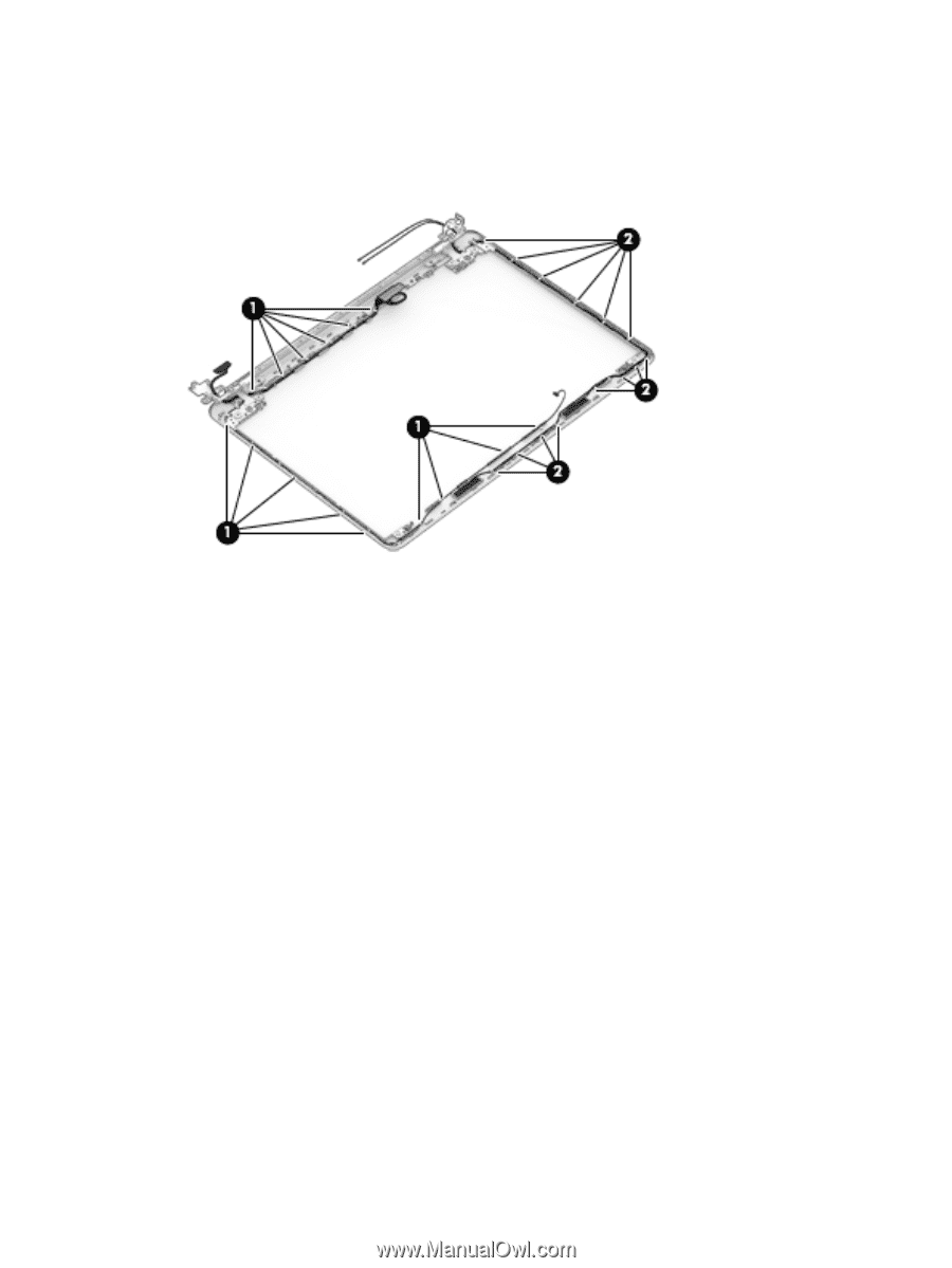
7.
If replacing the display enclosure, be sure that the subcomponents (including the camera/microphone
module, the antenna receivers, and all associated cables and hardware) are transferred to the new
enclosure.
Use the following image to determine proper display cable
(1)
and antenna cable
(2)
routing.
Reverse this procedure to reassemble and install the display assembly.
62
Chapter 5
Removal and replacement procedures for Authorized Service Provider parts