HP 14-bp100 Maintenance and Service Guide - Page 59
System board
 |
View all HP 14-bp100 manuals
Add to My Manuals
Save this manual to your list of manuals |
Page 59 highlights
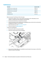
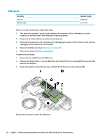
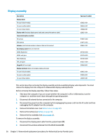
System board NOTE: The system board spare part kit includes replacement thermal materials. Description System board (includes replacement thermal materials): All system boards use the following part numbers: xxxxxx-001: Non-Windows operating systems xxxxxx-601: Windows 10 operating system For use in models with discrete graphics memory: ● Intel Core i7-7500U processor and 2 GB of discrete graphics memory ● Intel Core i5-8250U processor and 2 GB of discrete graphics memory ● Intel Core i5-7200U processor and 2 GB of discrete graphics memory For use in models with UMA graphics memory: ● Intel Core i7-7500U processor ● Intel Core i5-7200U processor ● Intel Core i3-7100U processor ● Intel Core i3-6006U processor ● Intel Pentium 4415U processor ● Intel Pentium N3710 processor ● Intel Pentium N3710 processor (models with 64 GB eMMC memory) ● Intel Celeron N3060 processor ● Intel Celeron N3060 processor (models with 64 GB eMMC memory) Spare part number 929562-xx1 934785-xx1 929563-xx1 927264-xx1 927265-xx1 927266-xx1 935889-xx1 927267-xx1 929564-xx1 934789-xx1 929565-xx1 L00745-xx1 Before removing the system board, follow these steps: 1. Shut down the computer. If you are unsure whether the computer is off or in Hibernation, turn the computer on, and then shut it down through the operating system. 2. Disconnect all external devices connected to the computer. 3. Disconnect the power from the computer by first unplugging the power cord from the AC outlet and then unplugging the AC adapter from the computer. 4. Remove the bottom cover (see Bottom cover on page 32). 5. Remove the battery (see Battery on page 34). 6. Remove the WLAN module (see WLAN module on page 35). 7. Remove the memory module (see Memory module on page 37). 8. Remove the hard drive (see Hard drive on page 38). 9. Remove the solid-state drive (see Solid-state drive (SSD) on page 40). 10. Remove the fan assembly (see Fan on page 42). Component replacement procedures 51
-
 1
1 -
2
-
3
-
4
-
5
-
6
-
7
-
8
-
9
-
10
-
11
-
12
-
13
-
14
-
15
-
16
-
17
-
18
-
19
-
20
-
21
-
22
-
23
-
24
-
25
-
26
-
27
-
28
-
29
-
30
-
31
-
32
-
33
-
34
-
35
-
36
-
37
-
38
-
39
-
40
-
41
-
42
-
43
-
44
-
45
-
46
-
47
-
48
-
49
-
50
-
51
-
52
-
53
-
 54
54 -
 55
55 -
 56
56 -
 57
57 -
 58
58 -
 59
59 -
 60
60 -
 61
61 -
 62
62 -
 63
63 -
 64
64 -
65
-
66
-
67
-
68
-
69
-
70
-
71
-
72
-
73
-
74
-
75
-
76
-
77
-
78
-
79
-
80
-
81
-
82
-
83
-
84
-
85
-
86
-
87
-
88
-
89
-
90
-
91
-
92
-
93
-
94
-
95
-
96
-
97
-
98
 |
 |
