HP 14-bp100 Maintenance and Service Guide - Page 69
To remove the display/camera cable, disconnect the cable from the board at the bottom of the display
 |
View all HP 14-bp100 manuals
Add to My Manuals
Save this manual to your list of manuals |
Page 69 highlights
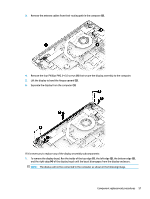
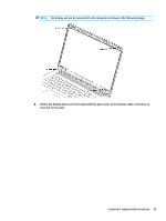
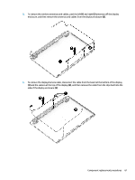
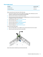
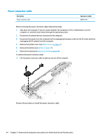
5. To remove the wireless antennas and cables, peel the left(1) and right (2) antennas off the display enclosure, and then remove the antennas and cables from the display enclosure (2). 6. To remove the display/camera cable, disconnect the cable from the board at the bottom of the display (1) and the camera at the top of the display (2), and then remove the cable from the clips built into the side of the display enclosure (3). Component replacement procedures 61
-
 1
1 -
2
-
3
-
4
-
5
-
6
-
7
-
8
-
9
-
10
-
11
-
12
-
13
-
14
-
15
-
16
-
17
-
18
-
19
-
20
-
21
-
22
-
23
-
24
-
25
-
26
-
27
-
28
-
29
-
30
-
31
-
32
-
33
-
34
-
35
-
36
-
37
-
38
-
39
-
40
-
41
-
42
-
43
-
44
-
45
-
46
-
47
-
48
-
49
-
50
-
51
-
52
-
53
-
54
-
55
-
56
-
57
-
58
-
59
-
60
-
61
-
62
-
63
-
 64
64 -
 65
65 -
 66
66 -
 67
67 -
 68
68 -
 69
69 -
 70
70 -
 71
71 -
 72
72 -
 73
73 -
 74
74 -
75
-
76
-
77
-
78
-
79
-
80
-
81
-
82
-
83
-
84
-
85
-
86
-
87
-
88
-
89
-
90
-
91
-
92
-
93
-
94
-
95
-
96
-
97
-
98
 |
 |
5.
To remove the wireless antennas and cables, peel the left
(1)
and right
(2)
antennas
off
the display
enclosure, and then remove the antennas and cables from the display enclosure
(2)
.
6.
To remove the display/camera cable, disconnect the cable from the board at the bottom of the display
(1)
and the camera at the top of the display
(2)
, and then remove the cable from the clips built into the
side of the display enclosure
(3)
.
Component replacement procedures
61