HP 14-bp100 Maintenance and Service Guide - Page 65
the bottom edge, the inside of the top edge
 |
View all HP 14-bp100 manuals
Add to My Manuals
Save this manual to your list of manuals |
Page 65 highlights
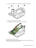
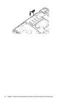
3. Remove the antenna cables from their routing path in the computer (3). 4. Remove the four Phillips PM2.5×6.0 screws (1) that secure the display assembly to the computer. 5. Lift the display to bend the hinges upward (2). 6. Separate the display from the computer (3). If it is necessary to replace any of the display assembly subcomponents: 1. To remove the display bezel, flex the inside of the top edge (1), the left edge (2), the bottom edge (3), and the right edge (4) of the display bezel until the bezel disengages from the display enclosure. NOTE: The display will not be connected to the computer as shown in the following image. Component replacement procedures 57
-
 1
1 -
2
-
3
-
4
-
5
-
6
-
7
-
8
-
9
-
10
-
11
-
12
-
13
-
14
-
15
-
16
-
17
-
18
-
19
-
20
-
21
-
22
-
23
-
24
-
25
-
26
-
27
-
28
-
29
-
30
-
31
-
32
-
33
-
34
-
35
-
36
-
37
-
38
-
39
-
40
-
41
-
42
-
43
-
44
-
45
-
46
-
47
-
48
-
49
-
50
-
51
-
52
-
53
-
54
-
55
-
56
-
57
-
58
-
59
-
 60
60 -
 61
61 -
 62
62 -
 63
63 -
 64
64 -
 65
65 -
 66
66 -
 67
67 -
 68
68 -
 69
69 -
 70
70 -
71
-
72
-
73
-
74
-
75
-
76
-
77
-
78
-
79
-
80
-
81
-
82
-
83
-
84
-
85
-
86
-
87
-
88
-
89
-
90
-
91
-
92
-
93
-
94
-
95
-
96
-
97
-
98
 |
 |
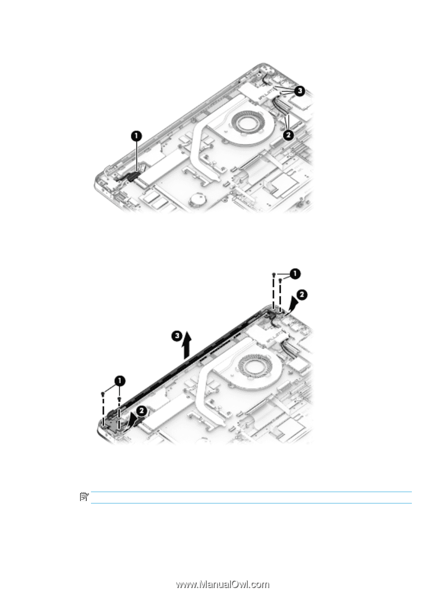
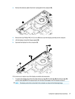
3.
Remove the antenna cables from their routing path in the computer
(3)
.
4.
Remove the four Phillips PM2.5×6.0 screws
(1)
that secure the display assembly to the computer.
5.
Lift the display to bend the hinges upward
(2)
.
6.
Separate the display from the computer
(3)
.
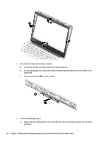
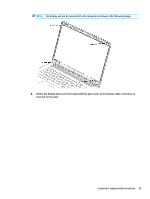
If it is necessary to replace any of the display assembly subcomponents:
1.
To remove the display bezel,
flex
the inside of the top edge
(1)
, the left edge
(2)
, the bottom edge
(3)
,
and the right edge
(4)
of the display bezel until the bezel disengages from the display enclosure.
NOTE:
The display will not be connected to the computer as shown in the following image.
Component replacement procedures
57