HP 14-bp100 Maintenance and Service Guide - Page 64
Display assembly, Description, Spare part number, Display bezel, Display cable
 |
View all HP 14-bp100 manuals
Add to My Manuals
Save this manual to your list of manuals |
Page 64 highlights
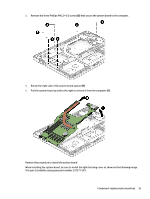
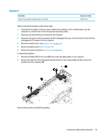
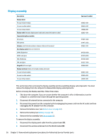
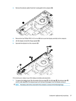
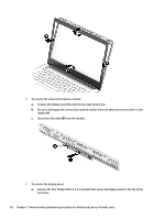
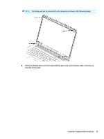
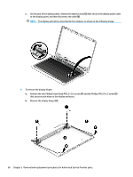
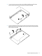
Display assembly Description Display bezel For use in black models For use in white models For use in blue models Display cable (includes display panel cable and camera/microphone cable) Camera/microphone module HD camera VGA camera Antenna, dual (includes wireless antenna cable and transceiver) Raw display panel (35.6-cm [14.0-in]) UWVA, Brightview UWVA, anti glare SVA, Brightview SVA, anti glare Hinge Kit (left and right) Display enclosure:(does not include wireless antennas) For use in black models For use in white models For use in blue models Spare part number 929635-001 929636-001 L00444-001 929637-001 919471-002 919472-002 929632-001 847660-008 821816-005 847664-008 916357-004 929640-001 929633-001 929634-001 L00445-001 This section describes removing the display assembly and disassembling display subcomponents. You must remove the display from the computer to disassemble display subcomponents. Before removing the display assembly, follow these steps: 1. Shut down the computer. If you are unsure whether the computer is off or in Hibernation, turn the computer on, and then shut it down through the operating system. 2. Disconnect all external devices connected to the computer. 3. Disconnect the power from the computer by first unplugging the power cord from the AC outlet and then unplugging the AC adapter from the computer. 4. Remove the bottom cover (see Bottom cover on page 32). 5. Remove the battery (see Battery on page 34). 6. Remove the fan assembly (see Fan on page 42). To remove the display assembly: 1. Disconnect the display panel cable from the system board (1). 2. Disconnect the wireless antennas from the WLAN module (2). 56 Chapter 5 Removal and replacement procedures for Authorized Service Provider parts
-
 1
1 -
2
-
3
-
4
-
5
-
6
-
7
-
8
-
9
-
10
-
11
-
12
-
13
-
14
-
15
-
16
-
17
-
18
-
19
-
20
-
21
-
22
-
23
-
24
-
25
-
26
-
27
-
28
-
29
-
30
-
31
-
32
-
33
-
34
-
35
-
36
-
37
-
38
-
39
-
40
-
41
-
42
-
43
-
44
-
45
-
46
-
47
-
48
-
49
-
50
-
51
-
52
-
53
-
54
-
55
-
56
-
57
-
58
-
 59
59 -
 60
60 -
 61
61 -
 62
62 -
 63
63 -
 64
64 -
 65
65 -
 66
66 -
 67
67 -
 68
68 -
 69
69 -
70
-
71
-
72
-
73
-
74
-
75
-
76
-
77
-
78
-
79
-
80
-
81
-
82
-
83
-
84
-
85
-
86
-
87
-
88
-
89
-
90
-
91
-
92
-
93
-
94
-
95
-
96
-
97
-
98
 |
 |