HP 14-bp100 Maintenance and Service Guide - Page 68
The display will not be connected to the computer as shown in the following image.
 |
View all HP 14-bp100 manuals
Add to My Manuals
Save this manual to your list of manuals |
Page 68 highlights
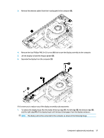
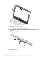
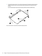
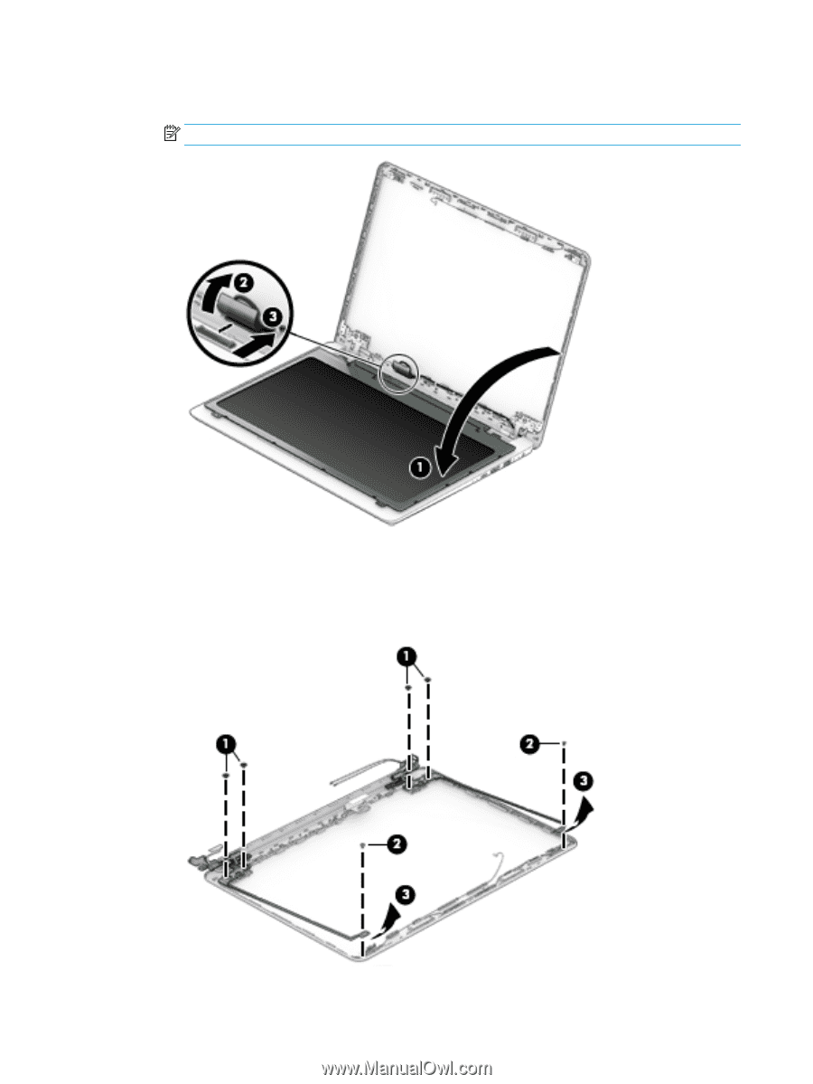
c. On the back of the display panel, release the adhesive strip (2) that secures the display panel cable to the display panel, and then disconnect the cable (3). NOTE: The display will not be connected to the computer as shown in the following image. 4. To remove the display hinges: a. Remove the two Phillips broad head PM2.5×3.0 screws (1) and the Phillips PM2.0×2.5 screw (2) that secures each hinge to the display enclosure. b. Remove the display hinges (3). 60 Chapter 5 Removal and replacement procedures for Authorized Service Provider parts
-
 1
1 -
2
-
3
-
4
-
5
-
6
-
7
-
8
-
9
-
10
-
11
-
12
-
13
-
14
-
15
-
16
-
17
-
18
-
19
-
20
-
21
-
22
-
23
-
24
-
25
-
26
-
27
-
28
-
29
-
30
-
31
-
32
-
33
-
34
-
35
-
36
-
37
-
38
-
39
-
40
-
41
-
42
-
43
-
44
-
45
-
46
-
47
-
48
-
49
-
50
-
51
-
52
-
53
-
54
-
55
-
56
-
57
-
58
-
59
-
60
-
61
-
62
-
 63
63 -
 64
64 -
 65
65 -
 66
66 -
 67
67 -
 68
68 -
 69
69 -
 70
70 -
 71
71 -
 72
72 -
 73
73 -
74
-
75
-
76
-
77
-
78
-
79
-
80
-
81
-
82
-
83
-
84
-
85
-
86
-
87
-
88
-
89
-
90
-
91
-
92
-
93
-
94
-
95
-
96
-
97
-
98
 |
 |
c.
On the back of the display panel, release the adhesive strip
(2)
that secures the display panel cable
to the display panel, and then disconnect the cable
(3)
.
NOTE:
The display will not be connected to the computer as shown in the following image.
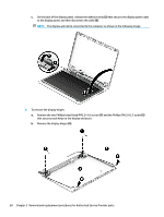
4.
To remove the display hinges:
a.
Remove the two Phillips broad head PM2.5×3.0 screws
(1)
and the Phillips PM2.0×2.5 screw
(2)
that secures each hinge to the display enclosure.
b.
Remove the display hinges
(3)
.
60
Chapter 5
Removal and replacement procedures for Authorized Service Provider parts