HP 625 Compaq 325 and 326 Notebook PCs HP 425 and 625 Notebook PCs - Maintenan - Page 100
System board, Heat sink see
 |
View all HP 625 manuals
Add to My Manuals
Save this manual to your list of manuals |
Page 100 highlights
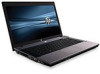
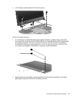
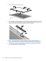
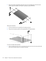
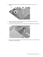
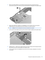
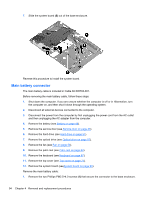
System board NOTE: The system board spare part kit includes replacement thermal material. Description System board with UMA graphics and RTC battery with RS880M chipset System board with discrete graphics and RTC battery with RS880M chipset Spare part number 611803-001 611802-001 Before removing the system board, follow these steps: 1. Shut down the computer. If you are unsure whether the computer is off or in Hibernation, turn the computer on, and then shut it down through the operating system. 2. Disconnect all external devices connected to the computer. 3. Disconnect the power from the computer by first unplugging the power cord from the AC outlet and then unplugging the AC adapter from the computer. 4. Remove the battery (see Battery on page 48). 5. Remove the service door (see Service door on page 49). 6. Remove the hard drive (see Hard drive on page 51). 7. Remove the optical drive (see Optical drive on page 57). 8. Remove the fan (see Fan on page 59). 9. Remove the palm rest (see Palm rest on page 64). 10. Remove the keyboard (see Keyboard on page 67). 11. Remove the top cover (see Top cover on page 71). When replacing the system board, be sure that the following components are removed from the defective system board and installed on the replacement system board: ● Memory module (see Memory module on page 54) ● WLAN module (see WLAN module on page 55) ● Modem module (see Modem module on page 97) ● Heat sink (see Heat sink on page 60) ● Processor (see Processor on page 62) ● Audio board (see Audio board on page 99) Remove the system board on a 39.6-cm (15.6-in) computer: 1. Position the computer with the front toward you. 2. Release the audio ZIF connector (1) and disconnect the cable (2) from the left edge of the system board. 90 Chapter 4 Removal and replacement procedures
-
 1
1 -
2
-
3
-
4
-
5
-
6
-
7
-
8
-
9
-
10
-
11
-
12
-
13
-
14
-
15
-
16
-
17
-
18
-
19
-
20
-
21
-
22
-
23
-
24
-
25
-
26
-
27
-
28
-
29
-
30
-
31
-
32
-
33
-
34
-
35
-
36
-
37
-
38
-
39
-
40
-
41
-
42
-
43
-
44
-
45
-
46
-
47
-
48
-
49
-
50
-
51
-
52
-
53
-
54
-
55
-
56
-
57
-
58
-
59
-
60
-
61
-
62
-
63
-
64
-
65
-
66
-
67
-
68
-
69
-
70
-
71
-
72
-
73
-
74
-
75
-
76
-
77
-
78
-
79
-
80
-
81
-
82
-
83
-
84
-
85
-
86
-
87
-
88
-
89
-
90
-
91
-
92
-
93
-
94
-
 95
95 -
 96
96 -
 97
97 -
 98
98 -
 99
99 -
 100
100 -
 101
101 -
 102
102 -
 103
103 -
 104
104 -
 105
105 -
106
-
107
-
108
-
109
-
110
-
111
-
112
-
113
-
114
-
115
-
116
-
117
-
118
-
119
-
120
-
121
-
122
-
123
-
124
-
125
-
126
-
127
-
128
-
129
-
130
-
131
-
132
-
133
-
134
-
135
-
136
-
137
-
138
-
139
-
140
-
141
-
142
-
143
-
144
-
145
-
146
-
147
-
148
-
149
-
150
-
151
-
152
-
153
-
154
-
155
-
156
-
157
-
158
 |
 |