HP 625 Compaq 325 and 326 Notebook PCs HP 425 and 625 Notebook PCs - Maintenan - Page 66
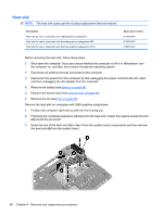
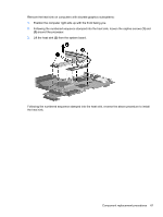
The edge of the module opposite the slot rises away from the computer., Remove the WLAN module
 |
View all HP 625 manuals
Add to My Manuals
Save this manual to your list of manuals |
Page 66 highlights
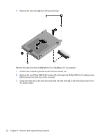
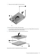
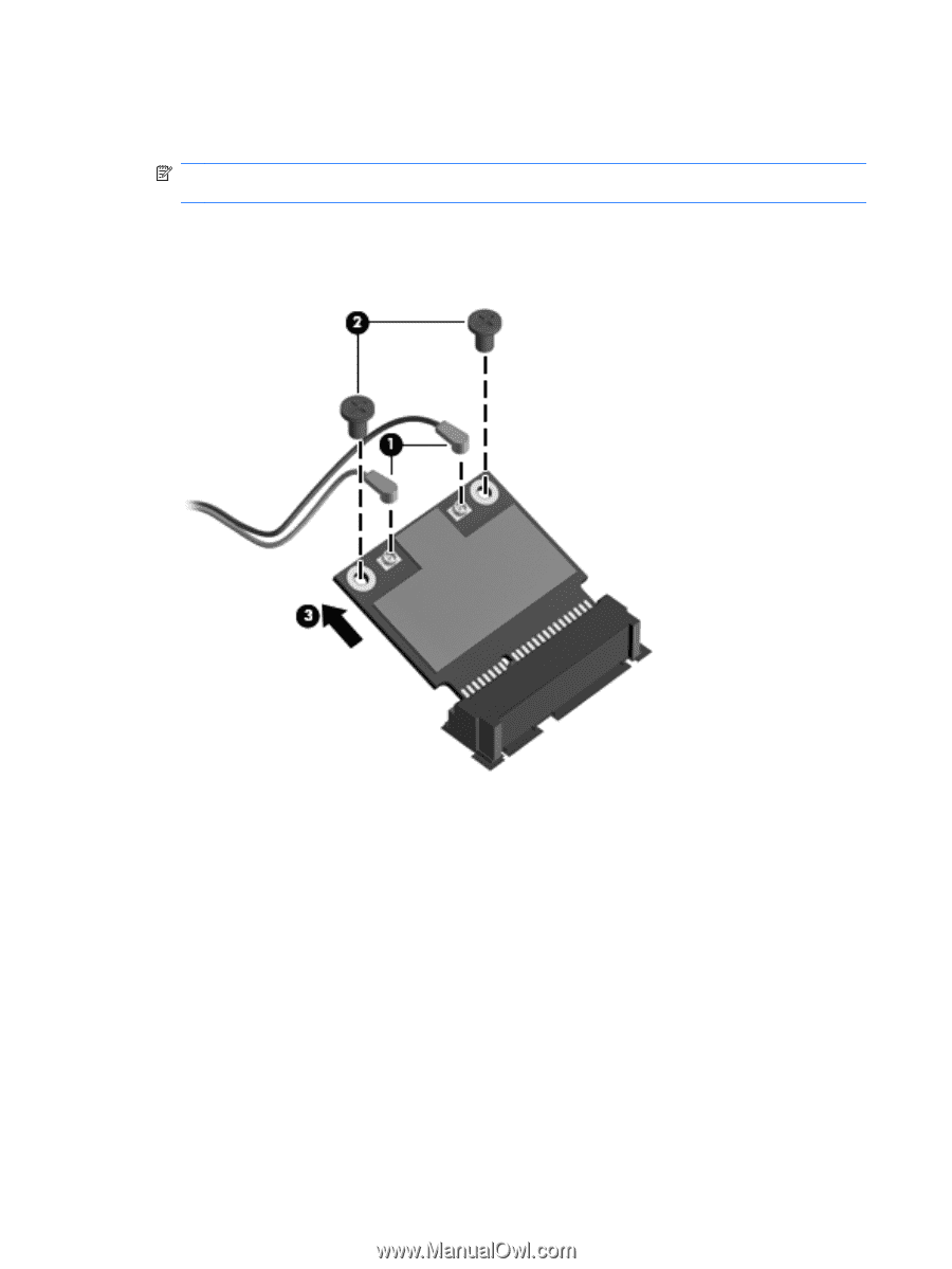
Remove the WLAN module: 1. Disconnect the WLAN antenna cables (1) from the terminals on the WLAN module. NOTE: The black WLAN antenna cable is connected to the WLAN module "Main" terminal. The white WLAN antenna cable is connected to the WLAN module "Aux" terminal. 2. Remove the two Phillips PM2.0×2.5 screws (2) that secure the WLAN module to the computer. (The edge of the module opposite the slot rises away from the computer.) 3. Remove the WLAN module (3) by pulling the module away from the slot at an angle. Reverse this procedure to install the WLAN module. 56 Chapter 4 Removal and replacement procedures
-
 1
1 -
2
-
3
-
4
-
5
-
6
-
7
-
8
-
9
-
10
-
11
-
12
-
13
-
14
-
15
-
16
-
17
-
18
-
19
-
20
-
21
-
22
-
23
-
24
-
25
-
26
-
27
-
28
-
29
-
30
-
31
-
32
-
33
-
34
-
35
-
36
-
37
-
38
-
39
-
40
-
41
-
42
-
43
-
44
-
45
-
46
-
47
-
48
-
49
-
50
-
51
-
52
-
53
-
54
-
55
-
56
-
57
-
58
-
59
-
60
-
 61
61 -
 62
62 -
 63
63 -
 64
64 -
 65
65 -
 66
66 -
 67
67 -
 68
68 -
 69
69 -
 70
70 -
 71
71 -
72
-
73
-
74
-
75
-
76
-
77
-
78
-
79
-
80
-
81
-
82
-
83
-
84
-
85
-
86
-
87
-
88
-
89
-
90
-
91
-
92
-
93
-
94
-
95
-
96
-
97
-
98
-
99
-
100
-
101
-
102
-
103
-
104
-
105
-
106
-
107
-
108
-
109
-
110
-
111
-
112
-
113
-
114
-
115
-
116
-
117
-
118
-
119
-
120
-
121
-
122
-
123
-
124
-
125
-
126
-
127
-
128
-
129
-
130
-
131
-
132
-
133
-
134
-
135
-
136
-
137
-
138
-
139
-
140
-
141
-
142
-
143
-
144
-
145
-
146
-
147
-
148
-
149
-
150
-
151
-
152
-
153
-
154
-
155
-
156
-
157
-
158
 |
 |
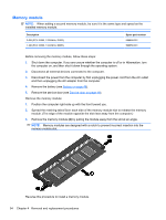
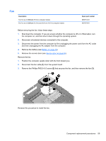
Remove the WLAN module:
1.
Disconnect the WLAN antenna cables
(1)
from the terminals on the WLAN module.
NOTE:
The black WLAN antenna cable is connected to the WLAN module “Main” terminal.
The white WLAN antenna cable is connected to the WLAN module “Aux” terminal.
2.
Remove the two Phillips PM2.0×2.5 screws
(2)
that secure the WLAN module to the computer.
(The edge of the module opposite the slot rises away from the computer.)
3.
Remove the WLAN module
(3)
by pulling the module away from the slot at an angle.
Reverse this procedure to install the WLAN module.
56
Chapter 4
Removal and replacement procedures