HP 625 Compaq 325 and 326 Notebook PCs HP 425 and 625 Notebook PCs - Maintenan - Page 70
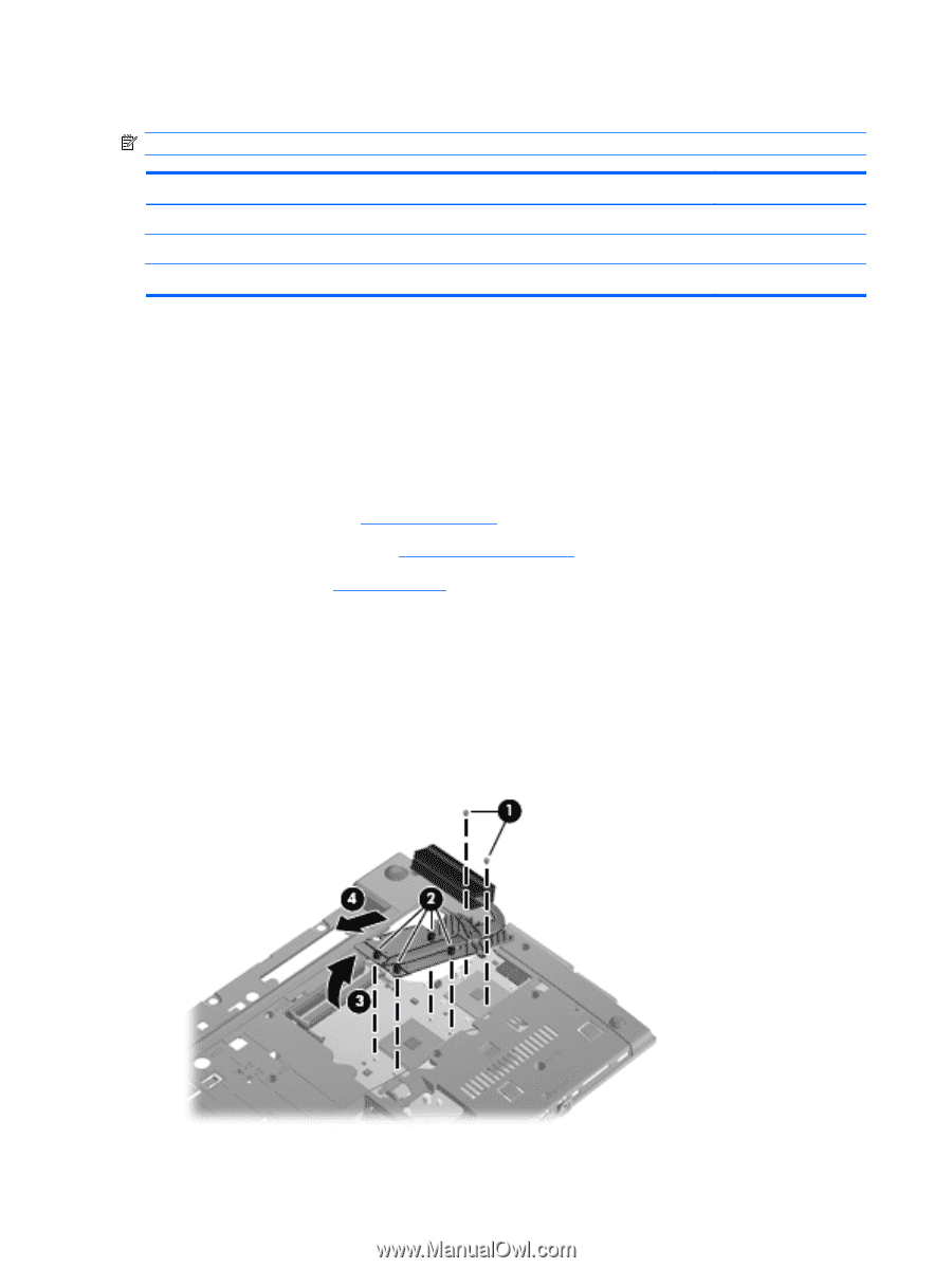
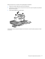
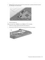
Heat sink, Following the numbered sequence stamped into the heat sink, loosen the captive screws
 |
View all HP 625 manuals
Add to My Manuals
Save this manual to your list of manuals |
Page 70 highlights
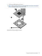
Heat sink NOTE: The heat sink spare part kit includes replacement thermal material. Description Heat sink for use in computers with UMA graphics subsystems Heat sink for use in computers with discrete graphics subsystems NB Heat sink for use in computers with discrete graphics subsystems CPU Spare part number 611804-001 611805-001 615355-001 Before removing the heat sink, follow these steps: 1. Shut down the computer. If you are unsure whether the computer is off or in Hibernation, turn the computer on, and then shut it down through the operating system. 2. Disconnect all external devices connected to the computer. 3. Disconnect the power from the computer by first unplugging the power cord from the AC outlet and then unplugging the AC adapter from the computer. 4. Remove the battery (see Battery on page 48). 5. Remove the service door (see Service door on page 49). 6. Remove the fan (see Fan on page 59). Remove the heat sink on computers with UMA graphics subsystems: 1. Position the computer right-side up with the front facing you. 2. Following the numbered sequence stamped into the heat sink, loosen the captive screws (1) and (2) around the processor. 3. Raise the end of the heat sink (3) to free it from the system board components and then remove the heat sink (4) from the system board. 60 Chapter 4 Removal and replacement procedures
-
 1
1 -
2
-
3
-
4
-
5
-
6
-
7
-
8
-
9
-
10
-
11
-
12
-
13
-
14
-
15
-
16
-
17
-
18
-
19
-
20
-
21
-
22
-
23
-
24
-
25
-
26
-
27
-
28
-
29
-
30
-
31
-
32
-
33
-
34
-
35
-
36
-
37
-
38
-
39
-
40
-
41
-
42
-
43
-
44
-
45
-
46
-
47
-
48
-
49
-
50
-
51
-
52
-
53
-
54
-
55
-
56
-
57
-
58
-
59
-
60
-
61
-
62
-
63
-
64
-
 65
65 -
 66
66 -
 67
67 -
 68
68 -
 69
69 -
 70
70 -
 71
71 -
 72
72 -
 73
73 -
 74
74 -
 75
75 -
76
-
77
-
78
-
79
-
80
-
81
-
82
-
83
-
84
-
85
-
86
-
87
-
88
-
89
-
90
-
91
-
92
-
93
-
94
-
95
-
96
-
97
-
98
-
99
-
100
-
101
-
102
-
103
-
104
-
105
-
106
-
107
-
108
-
109
-
110
-
111
-
112
-
113
-
114
-
115
-
116
-
117
-
118
-
119
-
120
-
121
-
122
-
123
-
124
-
125
-
126
-
127
-
128
-
129
-
130
-
131
-
132
-
133
-
134
-
135
-
136
-
137
-
138
-
139
-
140
-
141
-
142
-
143
-
144
-
145
-
146
-
147
-
148
-
149
-
150
-
151
-
152
-
153
-
154
-
155
-
156
-
157
-
158
 |
 |