HP 625 Compaq 325 and 326 Notebook PCs HP 425 and 625 Notebook PCs - Maintenan - Page 104
Main battery connector, Remove the keyboard see
 |
View all HP 625 manuals
Add to My Manuals
Save this manual to your list of manuals |
Page 104 highlights
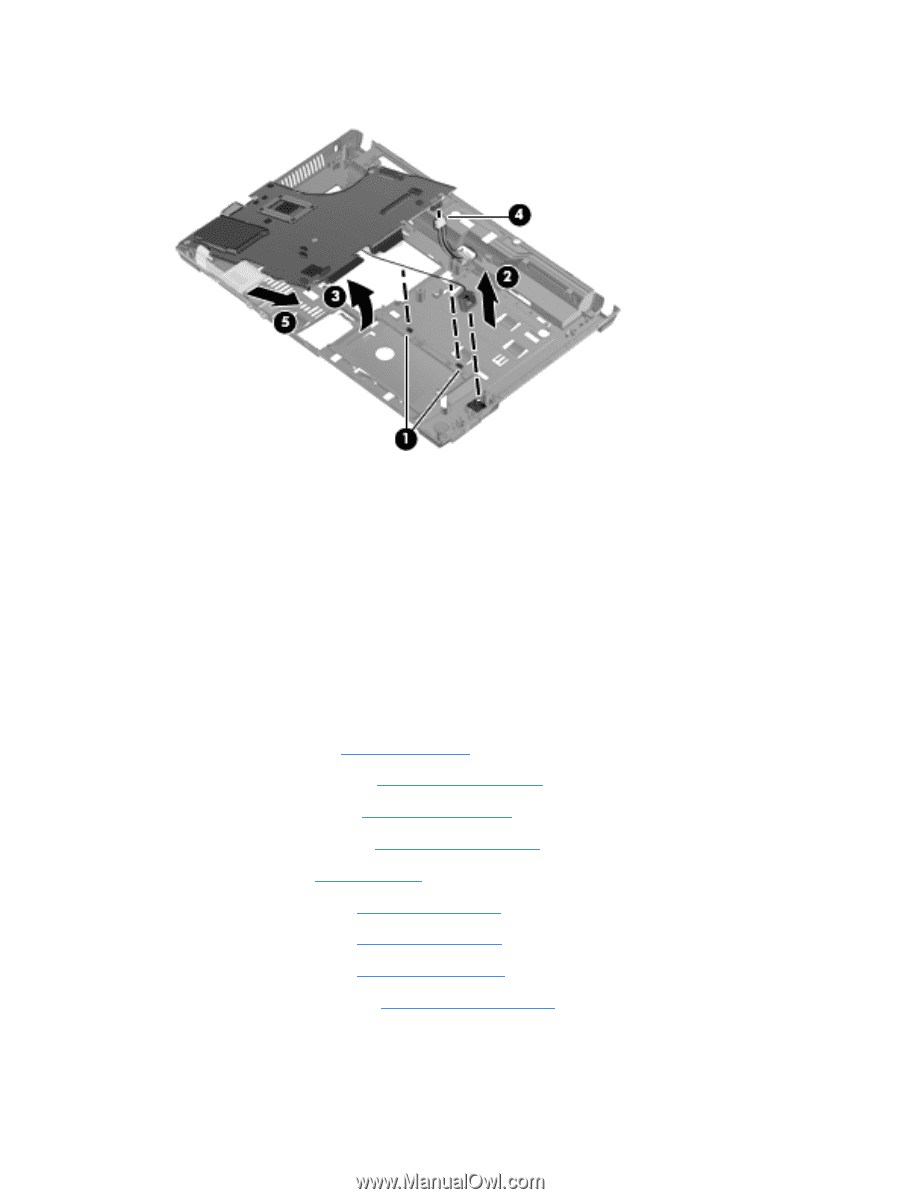
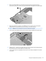
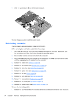
7. Slide the system board (5) out of the base enclosure. Reverse this procedure to install the system board. Main battery connector The main battery cable is included in Cable Kit 605793-001. Before removing the main battery cable, follow these steps: 1. Shut down the computer. If you are unsure whether the computer is off or in Hibernation, turn the computer on, and then shut it down through the operating system. 2. Disconnect all external devices connected to the computer. 3. Disconnect the power from the computer by first unplugging the power cord from the AC outlet and then unplugging the AC adapter from the computer. 4. Remove the battery (see Battery on page 48). 5. Remove the service door (see Service door on page 49). 6. Remove the hard drive (see Hard drive on page 51). 7. Remove the optical drive (see Optical drive on page 57). 8. Remove the fan (see Fan on page 59). 9. Remove the palm rest (see Palm rest on page 64). 10. Remove the keyboard (see Keyboard on page 67). 11. Remove the top cover (see Top cover on page 71). 12. Remove the system board (seeSystem board on page 90). Remove the main battery cable: 1. Remove the two Phillips PM2.5×4.0 screws (1) that secure the connector to the base enclosure. 94 Chapter 4 Removal and replacement procedures
-
 1
1 -
2
-
3
-
4
-
5
-
6
-
7
-
8
-
9
-
10
-
11
-
12
-
13
-
14
-
15
-
16
-
17
-
18
-
19
-
20
-
21
-
22
-
23
-
24
-
25
-
26
-
27
-
28
-
29
-
30
-
31
-
32
-
33
-
34
-
35
-
36
-
37
-
38
-
39
-
40
-
41
-
42
-
43
-
44
-
45
-
46
-
47
-
48
-
49
-
50
-
51
-
52
-
53
-
54
-
55
-
56
-
57
-
58
-
59
-
60
-
61
-
62
-
63
-
64
-
65
-
66
-
67
-
68
-
69
-
70
-
71
-
72
-
73
-
74
-
75
-
76
-
77
-
78
-
79
-
80
-
81
-
82
-
83
-
84
-
85
-
86
-
87
-
88
-
89
-
90
-
91
-
92
-
93
-
94
-
95
-
96
-
97
-
98
-
 99
99 -
 100
100 -
 101
101 -
 102
102 -
 103
103 -
 104
104 -
 105
105 -
 106
106 -
 107
107 -
 108
108 -
 109
109 -
110
-
111
-
112
-
113
-
114
-
115
-
116
-
117
-
118
-
119
-
120
-
121
-
122
-
123
-
124
-
125
-
126
-
127
-
128
-
129
-
130
-
131
-
132
-
133
-
134
-
135
-
136
-
137
-
138
-
139
-
140
-
141
-
142
-
143
-
144
-
145
-
146
-
147
-
148
-
149
-
150
-
151
-
152
-
153
-
154
-
155
-
156
-
157
-
158
 |
 |