HP 625 Compaq 325 and 326 Notebook PCs HP 425 and 625 Notebook PCs - Maintenan - Page 89
USB connector assembly, 6-in computers
 |
View all HP 625 manuals
Add to My Manuals
Save this manual to your list of manuals |
Page 89 highlights
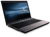
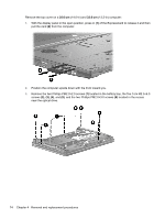
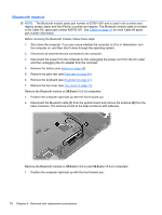
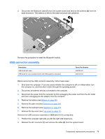
2. Disconnect the Bluetooth cable (1) from the system board and remove the antenna (2) from the base enclosure. The antenna is held to the base enclosure with adhesive. Reverse this procedure to install the Bluetooth module. USB connector assembly Description USB board with cable USB board for use on system boards with UMA graphics subsystem Spare Part Number 605796-001 622615-001 Before removing the USB connector assembly, follow these steps: 1. Shut down the computer. If you are unsure whether the computer is off or in Hibernation, turn the computer on, and then shut it down through the operating system. 2. Disconnect all external devices connected to the computer. 3. Disconnect the power from the computer by first unplugging the power cord from the AC outlet and then unplugging the AC adapter from the computer. 4. Remove the battery (see Battery on page 48). 5. Remove the palm rest (see Palm rest on page 64). 6. Remove the keyboard (see Keyboard on page 67). 7. Remove the top cover (see Top cover on page 71). Remove the USB connector assembly on 39.6-cm (15.6-in) computers: 1. Position the computer right-side up with the right side toward you. 2. Release the ZIF connector (1) and remove the cable (2) from the system board. Component replacement procedures 79
-
 1
1 -
2
-
3
-
4
-
5
-
6
-
7
-
8
-
9
-
10
-
11
-
12
-
13
-
14
-
15
-
16
-
17
-
18
-
19
-
20
-
21
-
22
-
23
-
24
-
25
-
26
-
27
-
28
-
29
-
30
-
31
-
32
-
33
-
34
-
35
-
36
-
37
-
38
-
39
-
40
-
41
-
42
-
43
-
44
-
45
-
46
-
47
-
48
-
49
-
50
-
51
-
52
-
53
-
54
-
55
-
56
-
57
-
58
-
59
-
60
-
61
-
62
-
63
-
64
-
65
-
66
-
67
-
68
-
69
-
70
-
71
-
72
-
73
-
74
-
75
-
76
-
77
-
78
-
79
-
80
-
81
-
82
-
83
-
 84
84 -
 85
85 -
 86
86 -
 87
87 -
 88
88 -
 89
89 -
 90
90 -
 91
91 -
 92
92 -
 93
93 -
 94
94 -
95
-
96
-
97
-
98
-
99
-
100
-
101
-
102
-
103
-
104
-
105
-
106
-
107
-
108
-
109
-
110
-
111
-
112
-
113
-
114
-
115
-
116
-
117
-
118
-
119
-
120
-
121
-
122
-
123
-
124
-
125
-
126
-
127
-
128
-
129
-
130
-
131
-
132
-
133
-
134
-
135
-
136
-
137
-
138
-
139
-
140
-
141
-
142
-
143
-
144
-
145
-
146
-
147
-
148
-
149
-
150
-
151
-
152
-
153
-
154
-
155
-
156
-
157
-
158
 |
 |
