HP 625 Compaq 325 and 326 Notebook PCs HP 425 and 625 Notebook PCs - Maintenan - Page 84
located in the battery bay, the five Torx M2.5×6.0, Remove the two Phillips PM2.0×2.0 screws
 |
View all HP 625 manuals
Add to My Manuals
Save this manual to your list of manuals |
Page 84 highlights
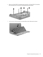
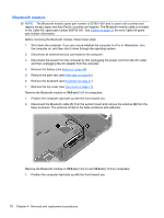
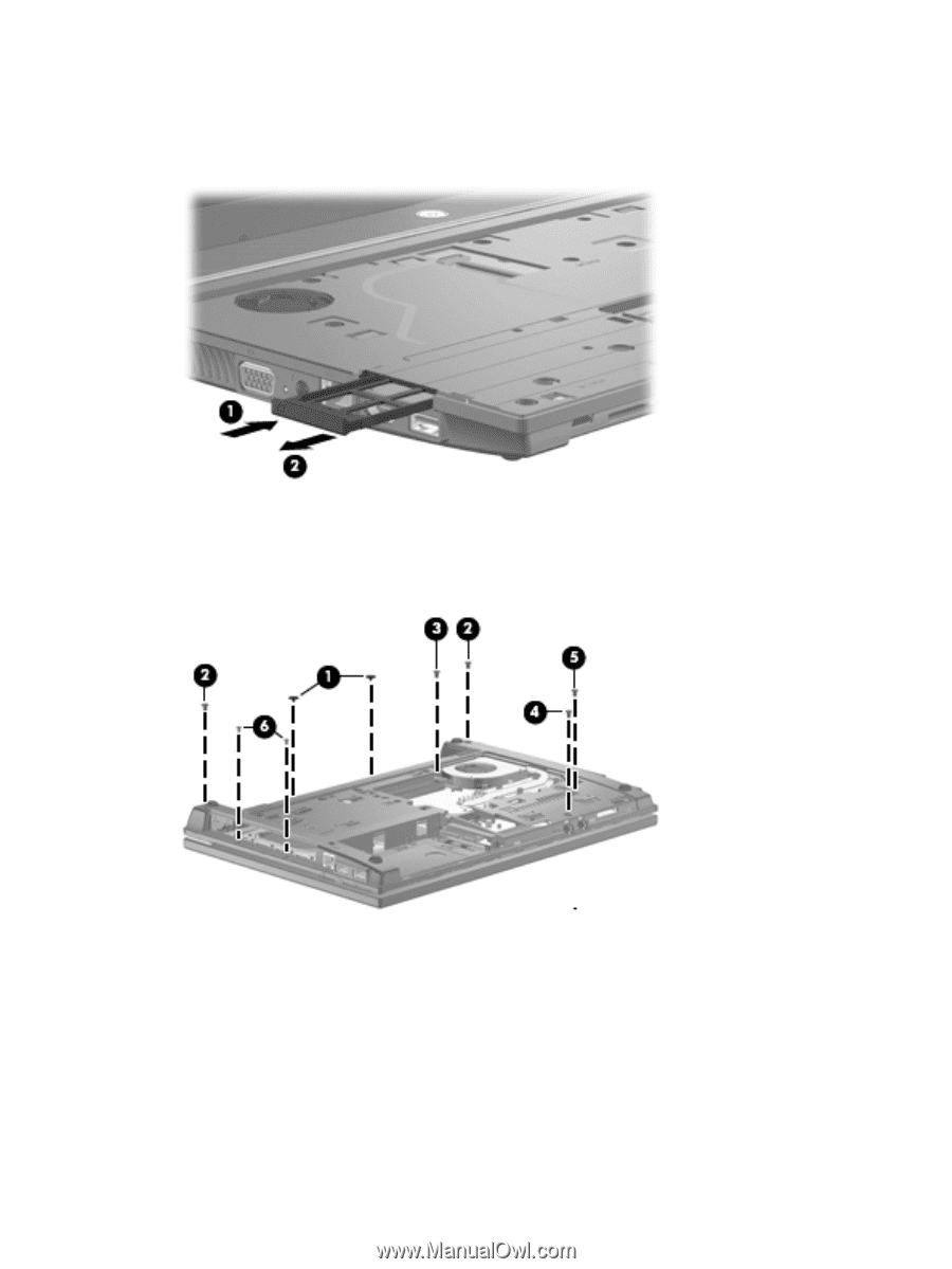
Remove the top cover on a 35.6-cm (14.0-in) and 33.8-cm (13.3-in) computer: 1. With the display panel in the open position, press in (1) of the ExpressCard to release it and then pull the card (2) from the computer. 2. Position the computer upside down with the front toward you. 3. Remove the two Phillips PM2.0×2.0 screws (1) located in the battery bay, the five Torx M2.5×6.0 screws (2), (3), (4), and (5), and the two Phillips PM2.0×3.0 screws (6) located in the recess near the optical drive. 74 Chapter 4 Removal and replacement procedures
-
 1
1 -
2
-
3
-
4
-
5
-
6
-
7
-
8
-
9
-
10
-
11
-
12
-
13
-
14
-
15
-
16
-
17
-
18
-
19
-
20
-
21
-
22
-
23
-
24
-
25
-
26
-
27
-
28
-
29
-
30
-
31
-
32
-
33
-
34
-
35
-
36
-
37
-
38
-
39
-
40
-
41
-
42
-
43
-
44
-
45
-
46
-
47
-
48
-
49
-
50
-
51
-
52
-
53
-
54
-
55
-
56
-
57
-
58
-
59
-
60
-
61
-
62
-
63
-
64
-
65
-
66
-
67
-
68
-
69
-
70
-
71
-
72
-
73
-
74
-
75
-
76
-
77
-
78
-
 79
79 -
 80
80 -
 81
81 -
 82
82 -
 83
83 -
 84
84 -
 85
85 -
 86
86 -
 87
87 -
 88
88 -
 89
89 -
90
-
91
-
92
-
93
-
94
-
95
-
96
-
97
-
98
-
99
-
100
-
101
-
102
-
103
-
104
-
105
-
106
-
107
-
108
-
109
-
110
-
111
-
112
-
113
-
114
-
115
-
116
-
117
-
118
-
119
-
120
-
121
-
122
-
123
-
124
-
125
-
126
-
127
-
128
-
129
-
130
-
131
-
132
-
133
-
134
-
135
-
136
-
137
-
138
-
139
-
140
-
141
-
142
-
143
-
144
-
145
-
146
-
147
-
148
-
149
-
150
-
151
-
152
-
153
-
154
-
155
-
156
-
157
-
158
 |
 |
Remove the top cover on a
35.6-cm
(14.0-in) and
33.8-cm
(13.3-in) computer:
1.
With the display panel in the open position, press in
(1)
of the ExpressCard to release it and then
pull the card
(2)
from the computer.
2.
Position the computer upside down with the front toward you.
3.
Remove the two Phillips PM2.0×2.0 screws
(1)
located in the battery bay, the five Torx M2.5×6.0
screws
(2), (3), (4)
, and
(5)
, and the two Phillips PM2.0×3.0 screws
(6)
located in the recess
near the optical drive.
74
Chapter 4
Removal and replacement procedures