HP 6715b HP Compaq 6715b and 6715s Notebook PC HP Compaq 6710b and 6710s Noteb - Page 100
Modem module, Remove the Phillips PM2.5×5.0 screw
 |
UPC - 883585514274
View all HP 6715b manuals
Add to My Manuals
Save this manual to your list of manuals |
Page 100 highlights
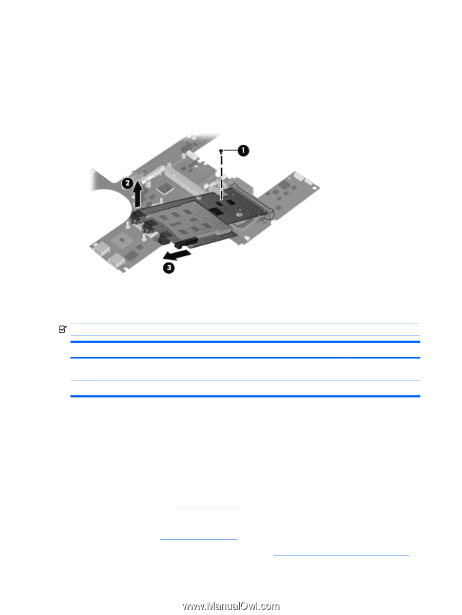
Remove the PC Card/audio board assembly: 1. Remove the Phillips PM2.5×5.0 screw (1) that secures the PC Card/audio board assembly to the system board. 2. Lift the left side of the PC Card/audio board assembly (2) until it disengages from the system board. 3. Remove the PC Card/audio board assembly (3) by pulling it away from the system board at an angle. Reverse this procedure to install the PC Card/audio board assembly. Modem module NOTE: All modem module spare part kits include a modem module cable. Description Spare part number For use with HP Compaq 6715 computer models and with HP Compaq 6710 computer models in 441074-001 all countries and regions except Japan and Asia/Pacific For use with HP Compaq 6710 computer models in Japan and Asia/Pacific countries and regions 449139-001 Before removing the modem module, follow these steps: 1. Shut down the computer. If you are unsure whether the computer is off or in Hibernation, turn the computer on, and then shut it down through the operating system. 2. Disconnect all external devices connected to the computer. 3. Disconnect the power from the computer by first unplugging the power cord from the AC outlet and then unplugging the AC adapter from the computer. 4. Remove the battery (see Battery on page 48). 5. Remove the following components: a. Hard drive (see Hard drive on page 52) b. Memory/WLAN module compartment cover (see Expansion memory module on page 56) 92 Chapter 4 Removal and replacement procedures
-
 1
1 -
2
-
3
-
4
-
5
-
6
-
7
-
8
-
9
-
10
-
11
-
12
-
13
-
14
-
15
-
16
-
17
-
18
-
19
-
20
-
21
-
22
-
23
-
24
-
25
-
26
-
27
-
28
-
29
-
30
-
31
-
32
-
33
-
34
-
35
-
36
-
37
-
38
-
39
-
40
-
41
-
42
-
43
-
44
-
45
-
46
-
47
-
48
-
49
-
50
-
51
-
52
-
53
-
54
-
55
-
56
-
57
-
58
-
59
-
60
-
61
-
62
-
63
-
64
-
65
-
66
-
67
-
68
-
69
-
70
-
71
-
72
-
73
-
74
-
75
-
76
-
77
-
78
-
79
-
80
-
81
-
82
-
83
-
84
-
85
-
86
-
87
-
88
-
89
-
90
-
91
-
92
-
93
-
94
-
 95
95 -
 96
96 -
 97
97 -
 98
98 -
 99
99 -
 100
100 -
 101
101 -
 102
102 -
 103
103 -
 104
104 -
 105
105 -
106
-
107
-
108
-
109
-
110
-
111
-
112
-
113
-
114
-
115
-
116
-
117
-
118
-
119
-
120
-
121
-
122
-
123
-
124
-
125
-
126
-
127
-
128
-
129
-
130
-
131
-
132
-
133
-
134
-
135
-
136
-
137
-
138
-
139
-
140
-
141
-
142
-
143
-
144
-
145
-
146
-
147
-
148
-
149
-
150
-
151
-
152
-
153
-
154
-
155
-
156
-
157
-
158
-
159
-
160
-
161
-
162
-
163
-
164
-
165
-
166
-
167
-
168
-
169
-
170
 |
 |