HP 6715b HP Compaq 6715b and 6715s Notebook PC HP Compaq 6710b and 6710s Noteb - Page 87
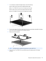
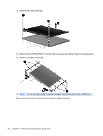
Remove the four Torx T8M2.5×6.0 screws, Remove the display bezel
 |
UPC - 883585514274
View all HP 6715b manuals
Add to My Manuals
Save this manual to your list of manuals |
Page 87 highlights
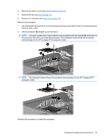
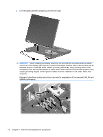
7. If it is necessary to replace the display hinges, remove the following: (1) Four rubber screw covers from the display bezel top edge (2) Four Torx T8M2.5×6.0 screws from the display bezel top edge (3) Two rubber screw covers from the display bezel bottom edge (4) Two Torx T8M2.5×7.0 screws from the display bezel top edge 8. Flex the inside edges of the left and right sides (1) and the top and bottom sides (2) of the display bezel until the bezel disengages from the display enclosure. 9. Remove the display bezel (3). NOTE: The display bezel is available using spare part number 446871-001. 10. Remove the four Torx T8M2.5×6.0 screws (1) that secure the display panel to the display enclosure. Component replacement procedures 79
-
 1
1 -
2
-
3
-
4
-
5
-
6
-
7
-
8
-
9
-
10
-
11
-
12
-
13
-
14
-
15
-
16
-
17
-
18
-
19
-
20
-
21
-
22
-
23
-
24
-
25
-
26
-
27
-
28
-
29
-
30
-
31
-
32
-
33
-
34
-
35
-
36
-
37
-
38
-
39
-
40
-
41
-
42
-
43
-
44
-
45
-
46
-
47
-
48
-
49
-
50
-
51
-
52
-
53
-
54
-
55
-
56
-
57
-
58
-
59
-
60
-
61
-
62
-
63
-
64
-
65
-
66
-
67
-
68
-
69
-
70
-
71
-
72
-
73
-
74
-
75
-
76
-
77
-
78
-
79
-
80
-
81
-
 82
82 -
 83
83 -
 84
84 -
 85
85 -
 86
86 -
 87
87 -
 88
88 -
 89
89 -
 90
90 -
 91
91 -
 92
92 -
93
-
94
-
95
-
96
-
97
-
98
-
99
-
100
-
101
-
102
-
103
-
104
-
105
-
106
-
107
-
108
-
109
-
110
-
111
-
112
-
113
-
114
-
115
-
116
-
117
-
118
-
119
-
120
-
121
-
122
-
123
-
124
-
125
-
126
-
127
-
128
-
129
-
130
-
131
-
132
-
133
-
134
-
135
-
136
-
137
-
138
-
139
-
140
-
141
-
142
-
143
-
144
-
145
-
146
-
147
-
148
-
149
-
150
-
151
-
152
-
153
-
154
-
155
-
156
-
157
-
158
-
159
-
160
-
161
-
162
-
163
-
164
-
165
-
166
-
167
-
168
-
169
-
170
 |
 |
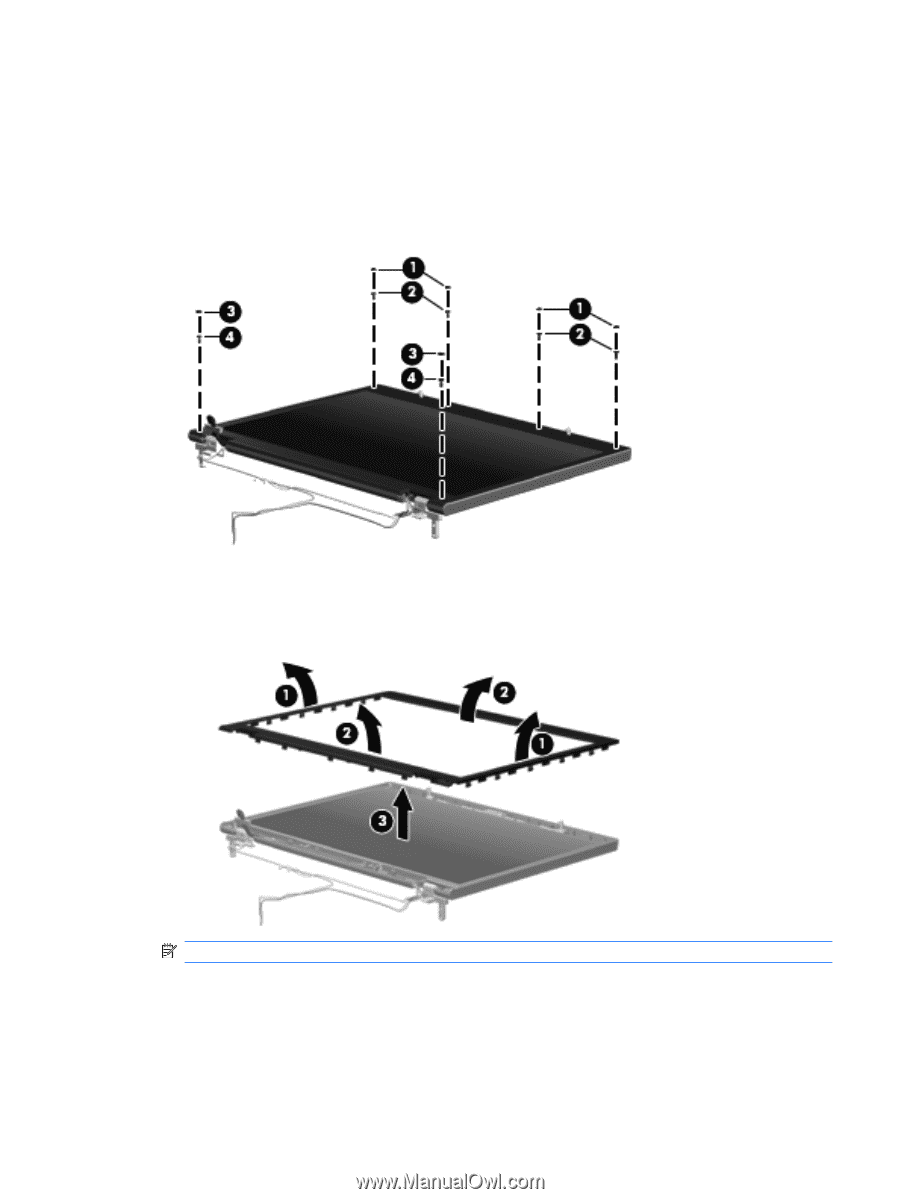
7.
If it is necessary to replace the display hinges, remove the following:
(1)
Four rubber screw covers from the display bezel top edge
(2)
Four Torx T8M2.5×6.0 screws from the display bezel top edge
(3)
Two rubber screw covers from the display bezel bottom edge
(4)
Two Torx T8M2.5×7.0 screws from the display bezel top edge
8.
Flex the inside edges of the left and right sides
(1)
and the top and bottom sides
(2)
of the display
bezel until the bezel disengages from the display enclosure.
9.
Remove the display bezel
(3)
.
NOTE:
The display bezel is available using spare part number 446871-001.
10.
Remove the four Torx T8M2.5×6.0 screws
(1)
that secure the display panel to the display
enclosure.
Component replacement procedures
79