HP 6715b HP Compaq 6715b and 6715s Notebook PC HP Compaq 6710b and 6710s Noteb - Page 97
Remove the system board
 |
UPC - 883585514274
View all HP 6715b manuals
Add to My Manuals
Save this manual to your list of manuals |
Page 97 highlights
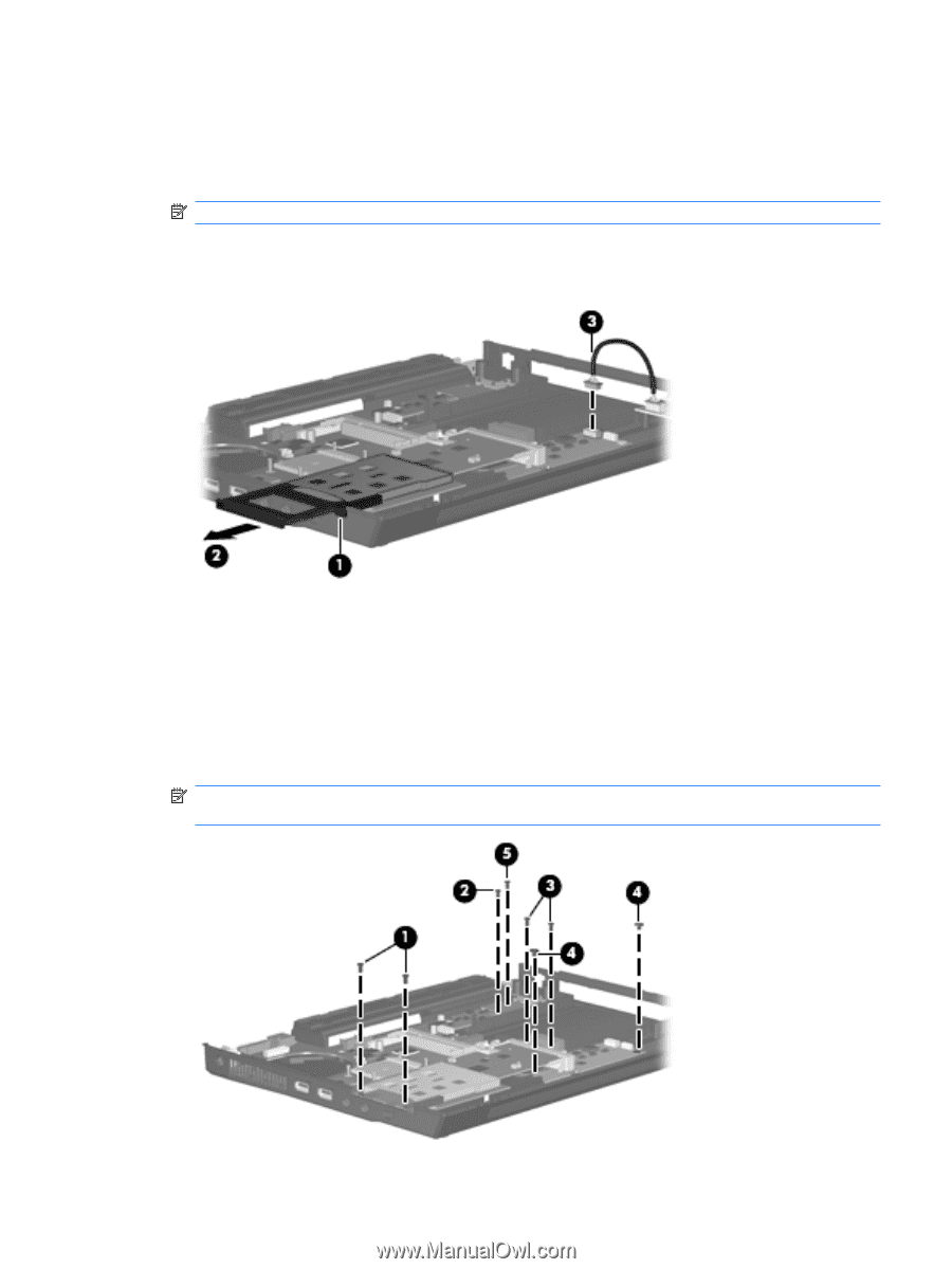
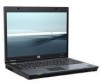
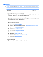
Remove the system board: 1. Press the PC Card eject button (1) twice. The first press releases the PC Card eject button from the PC Card slot. The second press releases the PC Card slot bezel from the PC Card slot. (The PC Card slot bezel is partially ejected from the PC Card slot.) NOTE: The PC Card slot bezel is included in the Plastics Kit, spare part number 443905-001. 2. Remove the PC Card slot bezel (2). 3. Disconnect the USB/Media Card Reader board cable (3) from the system board. 4. Remove the following screws: (1) Two Phillips PM2.5×5.0 screws that secure the system board and PC Card/audio board assembly (2) One Phillips PM2.5×5.0 screw that secures the system board (3) Two Phillips PM2.5×5.0 screws that secure the optical drive connector board (4) Two Phillips PM2.5×3.0 screws that secure the system board NOTE: If the computer is equipped with a WWAN module, another Phillips PM2.5×5.0 screw (5) that secures the SIM slot board must be removed. Component replacement procedures 89
-
 1
1 -
2
-
3
-
4
-
5
-
6
-
7
-
8
-
9
-
10
-
11
-
12
-
13
-
14
-
15
-
16
-
17
-
18
-
19
-
20
-
21
-
22
-
23
-
24
-
25
-
26
-
27
-
28
-
29
-
30
-
31
-
32
-
33
-
34
-
35
-
36
-
37
-
38
-
39
-
40
-
41
-
42
-
43
-
44
-
45
-
46
-
47
-
48
-
49
-
50
-
51
-
52
-
53
-
54
-
55
-
56
-
57
-
58
-
59
-
60
-
61
-
62
-
63
-
64
-
65
-
66
-
67
-
68
-
69
-
70
-
71
-
72
-
73
-
74
-
75
-
76
-
77
-
78
-
79
-
80
-
81
-
82
-
83
-
84
-
85
-
86
-
87
-
88
-
89
-
90
-
91
-
 92
92 -
 93
93 -
 94
94 -
 95
95 -
 96
96 -
 97
97 -
 98
98 -
 99
99 -
 100
100 -
 101
101 -
 102
102 -
103
-
104
-
105
-
106
-
107
-
108
-
109
-
110
-
111
-
112
-
113
-
114
-
115
-
116
-
117
-
118
-
119
-
120
-
121
-
122
-
123
-
124
-
125
-
126
-
127
-
128
-
129
-
130
-
131
-
132
-
133
-
134
-
135
-
136
-
137
-
138
-
139
-
140
-
141
-
142
-
143
-
144
-
145
-
146
-
147
-
148
-
149
-
150
-
151
-
152
-
153
-
154
-
155
-
156
-
157
-
158
-
159
-
160
-
161
-
162
-
163
-
164
-
165
-
166
-
167
-
168
-
169
-
170
 |
 |