HP 6715b HP Compaq 6715b and 6715s Notebook PC HP Compaq 6710b and 6710s Noteb - Page 78
Switch cover, board cable
 |
UPC - 883585514274
View all HP 6715b manuals
Add to My Manuals
Save this manual to your list of manuals |
Page 78 highlights
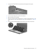
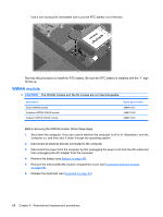
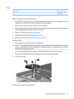
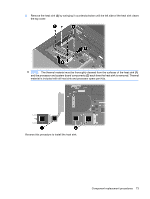
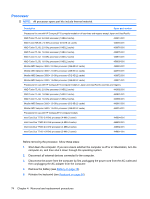
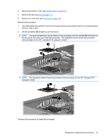
Switch cover Description Spare part number Switch cover for use with HP Compaq 6715b and 6710b computer models (includes power button 443911-001 board and cable and LED board and cable) Switch cover for use with HP Compaq 6715s and 6710s computer models (includes power button 443910-001 board and cable, but does not include LED board and cable) Before removing the switch cover, follow these steps: 1. Shut down the computer. If you are unsure whether the computer is off or in Hibernation, turn the computer on, and then shut it down through the operating system. 2. Disconnect all external devices connected to the computer. 3. Disconnect the power from the computer by first unplugging the power cord from the AC outlet and then unplugging the AC adapter from the computer. 4. Remove the battery (see Battery on page 48). 5. Release the keyboard (see Keyboard on page 64). Remove the switch cover: NOTE: Step 1 applies only to HP Compaq 6715b and 6710b computer models. 1. Release the ZIF connector (1) to which the LED board cable is attached and disconnect the LED board cable (2) from the system board. 2. Insert a flat-bladed tool into one of the four slots (3) in the switch cover and lift the switch cover (4) until it disengages from the computer. 3. Remove the switch cover. Reverse this procedure to install the switch cover. 70 Chapter 4 Removal and replacement procedures
-
 1
1 -
2
-
3
-
4
-
5
-
6
-
7
-
8
-
9
-
10
-
11
-
12
-
13
-
14
-
15
-
16
-
17
-
18
-
19
-
20
-
21
-
22
-
23
-
24
-
25
-
26
-
27
-
28
-
29
-
30
-
31
-
32
-
33
-
34
-
35
-
36
-
37
-
38
-
39
-
40
-
41
-
42
-
43
-
44
-
45
-
46
-
47
-
48
-
49
-
50
-
51
-
52
-
53
-
54
-
55
-
56
-
57
-
58
-
59
-
60
-
61
-
62
-
63
-
64
-
65
-
66
-
67
-
68
-
69
-
70
-
71
-
72
-
 73
73 -
 74
74 -
 75
75 -
 76
76 -
 77
77 -
 78
78 -
 79
79 -
 80
80 -
 81
81 -
 82
82 -
 83
83 -
84
-
85
-
86
-
87
-
88
-
89
-
90
-
91
-
92
-
93
-
94
-
95
-
96
-
97
-
98
-
99
-
100
-
101
-
102
-
103
-
104
-
105
-
106
-
107
-
108
-
109
-
110
-
111
-
112
-
113
-
114
-
115
-
116
-
117
-
118
-
119
-
120
-
121
-
122
-
123
-
124
-
125
-
126
-
127
-
128
-
129
-
130
-
131
-
132
-
133
-
134
-
135
-
136
-
137
-
138
-
139
-
140
-
141
-
142
-
143
-
144
-
145
-
146
-
147
-
148
-
149
-
150
-
151
-
152
-
153
-
154
-
155
-
156
-
157
-
158
-
159
-
160
-
161
-
162
-
163
-
164
-
165
-
166
-
167
-
168
-
169
-
170
 |
 |
