HP 6715b HP Compaq 6715b and 6715s Notebook PC HP Compaq 6710b and 6710s Noteb - Page 80
Heat sink, Remove the heat sink
 |
UPC - 883585514274
View all HP 6715b manuals
Add to My Manuals
Save this manual to your list of manuals |
Page 80 highlights
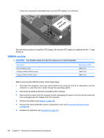
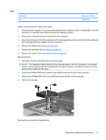
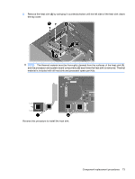
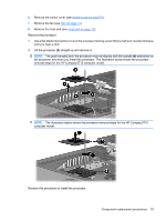
NOTE: To properly ventilate the computer, allow at least a 7.6-cm (3-inch) clearance on the left and right sides of the computer. The computer uses an electric fan for ventilation. The fan is controlled by a temperature sensor and is designed to turn on automatically when high temperature conditions exist. These conditions are affected by high external temperatures, system power consumption, power management/battery conservation configurations, battery fast charging, and software applications. Exhaust air is displaced through the ventilation grill located on the left side of the computer. Heat sink NOTE: All heat sink spare part kits include thermal material. Description For use with HP Compaq 6715 computer models For use with HP Compaq 6710 computer models Thermal Material Kit for use in all countries and regions except Japan and Asia/Pacific Thermal Material Kit for use in Japan and Asia/Pacific countries and regions Spare part number 443912-001 446920-001 413706-001 445853-001 Before removing the heat sink, follow these steps: 1. Shut down the computer. If you are unsure whether the computer is off or in Hibernation, turn the computer on, and then shut it down through the operating system. 2. Disconnect all external devices connected to the computer. 3. Disconnect the power from the computer by first unplugging the power cord from the AC outlet and then unplugging the AC adapter from the computer. 4. Remove the battery (see Battery on page 48). 5. Release the keyboard (see Keyboard on page 64). 6. Remove the switch cover (see Switch cover on page 70). 7. Remove the internal memory module (see Internal memory module on page 66). This step applies only to HP Compaq 6710 computer models. 8. Remove the fan (see Fan on page 71). Remove the heat sink: NOTE: Step 1 applies to HP Compaq 6715 computer models. The heat sink on HP Compaq 6710 computer models is secured to the computer by captive screws which must be loosened rather than removed. 1. Remove the four Phillips PM2.0×6.0 screws (1) that secure the heat sink to the system board. 2. Release the heat sink (2) by lifting the right side until it disengages from the processor. NOTE: Due to the adhesive quality of the thermal material located between the heat sink and processor, it may be necessary to move the heat sink from side to side to detach the heat sink from the processor. 72 Chapter 4 Removal and replacement procedures
-
 1
1 -
2
-
3
-
4
-
5
-
6
-
7
-
8
-
9
-
10
-
11
-
12
-
13
-
14
-
15
-
16
-
17
-
18
-
19
-
20
-
21
-
22
-
23
-
24
-
25
-
26
-
27
-
28
-
29
-
30
-
31
-
32
-
33
-
34
-
35
-
36
-
37
-
38
-
39
-
40
-
41
-
42
-
43
-
44
-
45
-
46
-
47
-
48
-
49
-
50
-
51
-
52
-
53
-
54
-
55
-
56
-
57
-
58
-
59
-
60
-
61
-
62
-
63
-
64
-
65
-
66
-
67
-
68
-
69
-
70
-
71
-
72
-
73
-
74
-
 75
75 -
 76
76 -
 77
77 -
 78
78 -
 79
79 -
 80
80 -
 81
81 -
 82
82 -
 83
83 -
 84
84 -
 85
85 -
86
-
87
-
88
-
89
-
90
-
91
-
92
-
93
-
94
-
95
-
96
-
97
-
98
-
99
-
100
-
101
-
102
-
103
-
104
-
105
-
106
-
107
-
108
-
109
-
110
-
111
-
112
-
113
-
114
-
115
-
116
-
117
-
118
-
119
-
120
-
121
-
122
-
123
-
124
-
125
-
126
-
127
-
128
-
129
-
130
-
131
-
132
-
133
-
134
-
135
-
136
-
137
-
138
-
139
-
140
-
141
-
142
-
143
-
144
-
145
-
146
-
147
-
148
-
149
-
150
-
151
-
152
-
153
-
154
-
155
-
156
-
157
-
158
-
159
-
160
-
161
-
162
-
163
-
164
-
165
-
166
-
167
-
168
-
169
-
170
 |
 |